165
Menu : Menu Description Tables
Me
n
u
The ____ in the Adjustable Range column indicates the
preset mode.
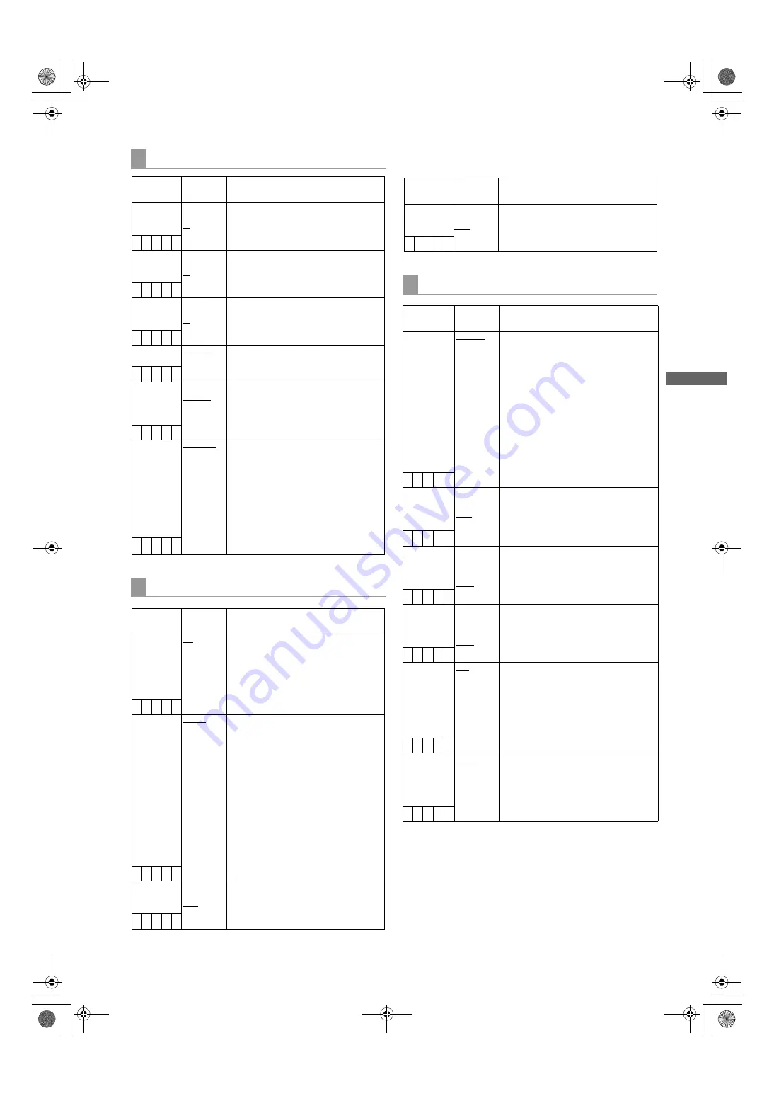
LCD MONITOR
Items/
Data Saved
Adjustable
Range
Remarks
BRIGHTNESS –7
:
+0
:
+7
Adjust the LCD monitor brightness.
– C U F –
COLOR
LEVEL
–7
:
+0
:
+7
Adjust the LCD monitor chroma level.
– C U F –
CONTRAST
–7
:
+0
:
+7
Adjust the LCD monitor contrast.
– C U F –
BACKLIGHT
NORMAL
HIGH
Adjust the backlight
NORMAL
:
Mode normally used
HIGH:
This is brighter than NORMAL
– C U F –
SELF SHOOT NORMAL
MIRROR
Select whether or not to change the
LCD monitor to mirror image.
NORMAL:
Do not change to mirror
image.
MIRROR:
Change to mirror image.
– C U F –
ASPECT
CONV.
SQUEEZE
LT.BOX
Select a screen ratio for images
displayed on the LCD monitor (In SD
mode only).
SQUEEZE:
Display images in the
squeeze size.
LT.BOX:
Display images in the letter
box size.
Note
This item is enabled only when ASPECT
described in “SYSTEM MODE” is set
to16:9.
– C U F –
GENLOCK
Items/
Data Saved
Adjustable
Range
Remarks
GENLOCK
INT
EXT
Switch the camera synchronising signal.
INT:
Synchronise with the internal
reference signal regardless of the
reference signal input to the
GENLOCK IN connector.
EXT:
Synchronise with the reference
signal input to the GENLOCK IN
connector.
– C U F R
GL PHASE
HD SDI
COMPOSIT
For selecting the output signals that lock
phases to the signals that are input in
the GENLOCK IN connector. (Only for
1080-59.94i, 1080-50i
)
HD SDI:
For locking the HD SDI signals to the
GENLOCK input.
For the down converter output
signals, the start position of the video
delays by about 90 lines.
COMPOSIT:
For locking the down converter output
signals to the GENLOCK input.
For the HD SDI output signals, the
start position of the video gains by
about 90 lines.
– C U F R
H PHASE
COARSE
–100
:
+000
:
+100
Perform coarse phase adjustment for
horizontal hold when configuring a
system.
– – – – –
Items/
Data Saved
Adjustable
Range
Remarks
H PHASE
FINE
–100
:
+000
:
+100
Perform fine phase adjustment for
horizontal hold when configuring a
system.
– – – – –
1394 SETTING
Items/
Data Saved
Adjustable
Range
Remarks
1394 AUDIO
OUT
CH1/CH2
CH3/CH4
For selecting the channels for audio
signals output from the DVCPRO
connector when the camera-recorder is
operating in DVCPRO or DV mode (for
480-59.94i or 576-50i only)
Note
When CH3/CH4 is selected, no sound is
heard in the following outputs:
z
EE output if the 25M REC CH SEL
menu option on the <MIC/AUDIO1>
screen on the MAIN OPERATION
page is set to 2CH.
z
Output of playback data recorded as
2-channel audio signals.
– C U F –
1394 SPEED
S100
S200
S400
For setting the transfer rate of signals
output from the DVCPRO connector.
S100:
100Mbps
S200:
200Mbps
S400:
400Mbps
– C U F –
1394 IN CH
0
:
63
AUTO
For setting the input channel of signals
input to the DVCPRO connector.
0 - 63:
To fix to the designated value
AUTO:
To follow the settings of the
externally connected devices
– C U F –
1394 OUT CH 0
:
63
AUTO
For setting the input channel of signals
output from the DVCPRO connector.
0 - 63:
To fix to the designated value
AUTO:
To follow the settings of the
externally connected devices
– C U F –
1394
CONTROL
OFF
BOTH
For setting the control for recording
start/stop operations of external devices
that are connected to the DVCPRO
connector.
OFF:
Do not control the externally
connected devices.
BOTH:
To control both the unit and the
externally connected devices
– C U F –
1394 CMD SEL REC_P
STOP
For setting the control of recording stop
operations of the external devices that
are connected to the DVCPRO
connector.
REC_P:
Operation to pause recording
STOP:
Stopping operation
– C U F –
AJ-HPX3000G(VQT1K82-5)E.book 165 ページ 2009年11月12日 木曜日 午後8時19分


