13
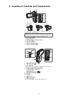
5 Location of Controls and Components
1
LCD monitor
It can open up to 90
Q
, rotate up to 180
Q
towards the lens or 105
Q
towards the opposite direction.
2
Power button [
]
3
Status indicator
4
Open/close lever [SD CARD/BATTERY]
5
Lock lever [LOCK]
6
Menu button [MENU]
7
REC/
button [REC/
]
8
Intelligent auto button [
]
Due to limitations in LCD production technology, there may be some
tiny bright or dark spots on the LCD monitor screen. However, this is
not a malfunction and does not affect the recorded picture.
1
2
8
3
7
6
4
5
Ɣ
9
Slow motion mode button [
]
10 Photoshot button [
]
11 SET button [SET]
Use the SET button to select the recording functions and playback
operations, and to operate the menu screen.
12 In Recording Mode: Zoom button [W/T]
In Playback Mode: Volume button
Zoom button [W/T]
Thumbnail display switch [
/
]
13 Recording start/stop button [
]
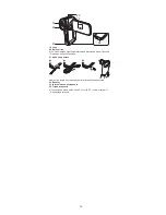
14 Rear door
15 Card slot
16 Battery holder
17 HDMI micro connector
18 USB/AV connector
Use the USB cable/AV cable (only the supplied cable).
9
10
11
12
18
17
16
15
14
13
Ɣ
Ɣ
Summary of Contents for HX-WA20EB
Page 10: ...10 4 Specifications ...
Page 11: ...11 ...
Page 12: ...12 ...
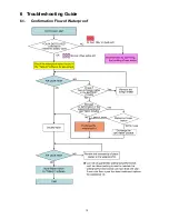
Page 15: ...15 6 Troubleshooting Guide 6 1 Confirmation Flow of Waterproof ...
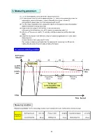
Page 16: ...16 6 2 Airtight Inspection with Air Leak Tester ...
Page 17: ...17 6 3 Air Leak Tester RFKZ0528 Operating Instruction ...
Page 18: ...18 ...
Page 19: ...19 ...
Page 20: ...20 ...
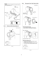
Page 24: ...24 8 3 1 Removal of the Top Ornament Fig D1 8 3 2 Removal of the Front Cabinet Unit Fig D2 ...
Page 25: ...25 8 3 3 Removal of the Side L Cabinet Unit Fig D3 Fig D4 ...
Page 26: ...26 Fig D5 Fig D6 8 3 4 Removal of the Battery Cover Fig D7 ...
Page 27: ...27 Fig D8 8 3 5 Removal of the Waterproof Rubber Fig D9 Fig D10 ...
Page 30: ...30 Fig D16 8 3 10 Removal of the Lens Holder Fig D17 8 3 11 Removal of the Speaker Fig D18 ...
Page 31: ...31 8 3 12 Removal of the LCD Unit Fig D19 Fig D20 ...
Page 32: ...32 Fig D21 Fig D22 ...
Page 33: ...33 Fig D23 8 3 13 Removal of the Hinge Cover LCD Case T Unit Fig D24 Fig D25 ...
Page 34: ...34 Fig D26 Fig D27 8 3 14 Removal of the LCD O Ring Fig D28 ...
Page 35: ...35 Fig D29 8 3 15 Removal of the LCD Panel Fig D30 ...
Page 36: ...36 Fig D31 8 3 16 Removal of the Mic Unit Monitor P C B Fig D32 Fig D33 ...
Page 37: ...37 Fig D34 8 3 17 Removal of the LCD Hinge Unit Fig D35 ...
Page 38: ...38 Fig D36 Fig D37 ...
Page 39: ...39 8 3 18 Removal of the Switch Unit Fig D38 Fig D39 ...
Page 40: ...40 Fig D40 ...
Page 43: ...43 10 Maintenance 10 1 Regular Maintenance Flow ...
Page 44: ...44 10 2 Component Kits of Waterproof ...
Page 50: ...Model No HX WA20 Schematic Diagram Note ...
Page 51: ...Model No HX WA20 Parts List Note ...
Page 52: ...Model No HX WA20 Main DMA Schematic Diagram Main P C B ...
Page 53: ...Model No HX WA20 Main PWA Schematic Diagram Main P C B ...
Page 54: ...Model No HX WA20 Main STA Schematic Diagram Main P C B ...
Page 55: ...Model No HX WA20 Monitor Schematic Diagram Monitor P C B ...
Page 56: ...Model No HX WA20 Main P C B Component Side ...
Page 57: ...Model No HX WA20 Main P C B Foil Side ...
Page 58: ...Model No HX WA20 Monitor P C B Component Side ...
Page 59: ...Model No HX WA20 Monitor P C B Foil Side ...
Page 66: ...Model No HX WA20 Frame and Casing Section 1 ...
Page 67: ...Model No HX WA20 Frame and Casing Section 2 ...
Page 68: ...Model No HX WA20 Packing Parts and Accessories Section ...


