background image

ORDER NO. MSBU0912001C0 

G20 

Service Manual 

JS-925 Series 

POS Workstation 

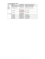
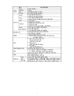
List of JS-925 series Product 

 Name 

Model 

Number. 

Remarks 

Main Unit  POS Workstation 

JS-925WS-010 

12inch type POS Workstation without 
HDD 
(Including HDD SATA Cable x 1) 

JS-925WS-050 

15inch type POS Workstation without 
HDD 
(Including HDD SATA Cable x 1) 

JS-925WS-051 

15inch type POS Workstation with HDD

JS-925WS-H50 

China Model 
15inch type POS Workstation without 
HDD 
 (Including HDD SATA Cable x 1) 
With AC Power Cable 

JS-925WS-H52 

China Model 
15inch type POS Workstation without 
HDD 
 (Including HDD SATA Cable x 1) 

With Rear Display & AC Power Cable


Option Unit  Communication Board 

JS-925CB-010 

IO extension Board 

JS-925CB-H10 

China Model 
IO extension Board 

Storage 
Unit 

USB HUB Board 

JS-925HU-010 

USB HUB Board 

Storage module Unit 

JS-925HD-010 

2.5 HDD module 
(Including HDD SATA Cable x 1) 

Storage module Unit 

JS-925SS-010 

2.5 SSD module 


© 2010 Panasonic System Networks Co., Ltd. 
All right reserved. Unauthorized copying and 
distribution is a violation of law.


V.1.14 (2010.11.5) 

Summary of Contents for JS-925WS-010

Page 1: ...station without HDD Including HDD SATA Cable x 1 With AC Power Cable JS 925WS H52 China Model 15inch type POS Workstation without HDD Including HDD SATA Cable x 1 With Rear Display AC Power Cable Option Unit Communication Board JS 925CB 010 IO extension Board JS 925CB H10 China Model IO extension Board Storage Unit USB HUB Board JS 925HU 010 USB HUB Board Storage module Unit JS 925HD 010 2 5 HDD m...

Page 2: ...le Rear Display Block Rear Display Unit JS 790RD 010 Rear Display module 2line AC cord Kit AC cord kit JS 950KT A25 or Spare Parts K2CG3EW00001 AC cord kit A AC cord kit JS 950KT E25 or Spare Parts YJKP30EPHA AC cord kit E AC cord kit JS 950KT F10 AC cord kit F AC cord kit JS 950KT K10 AC cord kit K AC cord kit JS 950KT UH0 AC cord kit UH AC cord kit JS 950KT W10 AC cord kit W AC cord kit JS 950KT...

Page 3: ...al public It does not contain warnings or cautions to advise non technical should be potential dangers in attempting to service a product Products powered by electricity should be serviced or repaired only by experienced professional technicians Any attempt to service or repair the product or products dealt with in this service information by anyone could result in serious injury or death ...

Page 4: ...ows Tool There is small discrepancy between e Diag base adjustment and Windows base adjustment 1 07 2010 2 26 149 163 176 Modified Replacement Parts List 1 08 2010 3 2 135 149 Added New parts 1 09 2010 4 1 149 150 176 Modified Replacement Parts List 1 10 2010 5 31 Cover 163 181 Deleted JS 950KT E10 JS 950KT A10 because they are not fitted to JS 925WS Corrected Parts Number Added Appendix JS 925HD ...

Page 5: ...n mode 26 3 4 Diagnosis item 28 3 4 1 Random Access Memory Test 28 3 4 2 Hard Disk Test 29 3 4 3 Video Test 30 3 4 4 Battery Test 34 3 4 5 Serial Port Test 36 3 4 6 Customer Display Test 38 3 4 7 System Information Test 39 3 4 8 Touch Panel Test 43 3 4 9 Drawer Test 47 3 4 10 Ether Test 50 3 4 11 USB test 50 3 4 12 AUDIO TEST 52 3 4 13 Backlight TEST 54 3 4 14 i Button TEST 55 3 4 15 Finger Print ...

Page 6: ...110 4 5 2 Parts Location 111 4 5 3 Replacement Parts List 115 5 Cable 116 6 Body Block 118 6 1 JS 925WS xxx Main Unit 118 6 1 1 Disassembly Drawing 118 6 1 2 Replacement Parts List 149 6 2 JS 925WS 050 051 LCD Unit 151 6 2 1 Disassembly Drawing 151 6 2 2 Replacement Parts List 163 6 3 JS 925WS 010 LCD Unit 164 6 3 1 Disassembly Drawing 164 6 3 2 Replacement Parts List 176 7 Trouble Shooting 177 Ap...

Page 7: ...as designed for Mid range Main Body was transplanted from JS 790WS LCD Unit was transplanted from JS 950WS Mother Board was re designed with new CPU Intel ATOM N270 1 6GHz For other detail specifications see the following Specifications ...

Page 8: ...B FDD boot USB CD ROM DVD ROM boot USB Flash Memory boot Supported OS Windows XP SP3 WEPOS 1 1 SP3 nicht unterstützen MFD POS Ready 2009 Windows Vista Ultimate Windows 7 Linux Kernel 2 6 Unterstützen OPOS HDD Type 2 5 HITACHI HTS545016B9A300 Size 160GB I F SATA 2 5 type SSD Type 2 5 Transcend TS8GSSD25S S Size 8GB I F SATA 2 5 type Other Disk Drive Option External USB FDD interface is supported Ex...

Page 9: ...I F For Communication board JS 925CB IO extension speaker Switch 1 Power Switch Power on off Hinweis Rasen Sie on off indem Sie eine kurze Periode schieben LED 1 Power 2 Colors green red Green ON Power ON Red ON Power OFF 1 HDD green Light ON HDD accessing 1 LAN green Light ON Send Receive Power Supply input AC100V 240V 50 60 Hz 1 6A Size 12 1 Approx W320mm x D263mm x H392mm 15 Approx W364mm x D29...

Page 10: ...S 925SS 010 Expansion SSD with SATA Cable Type 2 5 Transcend TS8GSSD25S S Size 8GB I F SATA 2 5 type Backup Battery Spare Parts Ni CD N4HKLNB00007 Ni MH BT50024A Battery Bracket YJ51 102470 Backup Battery for AC power fail Note Retention time 2 minutes Battery charge function Magnetic Card Reader JS 950MG 010 Magnetic strip reader module I F USB Internal connector Virtual COM Please see Service Ma...

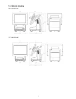
Page 11: ...5 1 3 Outside drawing 12 Touch Screen 15 Touch Screen ...

Page 12: ...upply state Green Power ON Red Soft Off LED2 LAN Green The light is on when accessing to LAN LED3 HDD Green The light is on when accessing to HDD USB 2 USB 1 Ethernet VGA USB 3 4 Option LINE OUT Option DIN Drawer 3 Option COM4 COM3 Speaker Option RJ Drawer 1 2 COM2 Powered COM1 Powered LAN LED HDD LED Power LED Soft Switch ...

Page 13: ... Port Positions USB 8 standard Inside of rear cover USB 6 standard For Display unit USB I F USB 7 Reserved For future use USB 5 standard Inside of front cover USB 3 4 Option IO Panel USB 1 2 standard IO Panel ...

Page 14: ... 6 DSR 2 RD 7 RTS 3 TD 8 CTS 4 DTR 9 RI default 5V 12V 5 GND By changing the setting of jumper pins on the PWB the 9 pin D SUB can receive either RI default or power supply 4 COM port COM3 COM4 9 pin D SUB Male PIN Signal PIN Signal 1 CD 6 DSR 2 RD 7 RTS 3 TD 8 CTS 4 DTR 9 RI 5 GND 5 Video 15 pin D SUB Female PIN Signal PIN Signal PIN Signal 1 Red 6 GND 11 NC 2 Green 7 GND 12 DCA_DAT 3 Blue 8 GND ...

Page 15: ...as Drawer is Opened when cable is disconnected or when either cash drawer is opened Limitation Two cash drawers must be connected concurrently in the case a special cable is used because CD 1 and 2 Status cannot be correct as the actual cash drawer status In other words it s not acceptable that either one cash drawer is used with a special cable Please refer to Appendix F RJ type Drawer I F also 8...

Page 16: ... COM Setting No 9 pin of COM1 2 can be changed as follows Jumper Setting JP271 for COM1 JP272 formCOM2 1 2 Short 5V 5V 3 4 Short RI Default RI Default 5 6 Short 12V 12V 2 JP141 Clear CMOS Jumper Setting 1 2 Short Default 2 3 Short Clear CMOS ...

Page 17: ...11 3 JP371 Battery Charging Voltage Setting Jumper Setting 1 2 Short For Current Battery 40ohm Default 2 3 Short For the future Battery ...

Page 18: ...2 CN 200 2 5 HDD SDD SATA I F Communication Board JS 795CB 010 PSU 85V 265V DC OUT 12V INLET W1 FG φ4 GST3 42R02 3212 300 K B L BROWN N WHITE FG GREEN AC Cord CN AC IN 1 2 5 C 1 2 5 C TP CNT board CN CN 15 INV or 12 INV CN CN CN 4 4 4 4 4 or 4 USB HUB board CN USB 6 4 MSR JIS 1 2 etc CN USB 3 4 CN SATA I F MASTER W5 W5 OPTION OPTION OPTION CN SATA I F SLAVE CN USB 8 7 7 CN USB 7 CUSTOMER DISPLAY V...

Page 19: ...RANSLATOR PCA9306 VSSOP8 1 U241 U242 U243 U244 YJ38 970001S IC TVS D ARRAY NUP4201MR6T1G TSOP6 W LF 4 U251 YJ32 975388S Regulator 1 2V Regulator for HDD Controller U253 Regulator RT9166A 12PGL 1 2V SOT 223 1 U252 YJ30 124166S HDD Controller HDD Controller ASIC IC 88SE6121B2 NAA2C000 QFN76 1 U261 YJ30 123324S Super I O Serial Controller for COM1 4 TP Customer Display IC ASIC LPC I O QFP128 W83627UH...

Page 20: ...r 24V Regulator for Cash Drawer TR N CHANNEL MOSFET FDS8896 SO 8 1 Q221 YJ35 339215S TR FET P CHANNEL APM2301AAC SOT 23 1 Q301 Q306 Q309 Q371 Q379 YJ35 390580S FET Q371 FET for TR MOSFET P CHANNEL FDS4435BZ SO 8 5 Q3011 YJ35 391734S TR MOSFET N CHANNEL STD60N3LH5 DPAK 1 Q304 YJ35 100066S TR NPN DTC143ZUA T106 SC 70 UMT3 1 Q307 YJ35 390130S TR FET P CHANNEL FDC604P_NL SSOT 6 1 Q311 Q312 Q335 YJ35 9...

Page 21: ...1 U252 U261 U271 U272 U281 U313 U321 U332 U341 Q332 Q217 Q371 Q311 Y201 Y251 24V for Cash Drawer generation area 5V generation area 3 3V generation area 1 5V for Chipset Core generation area U191 1 8V for Memory generation area ...

Page 22: ...14 U214 U291 U292 U322 1 5V generation area 0 9V for Memory Terminator generation area ...

Page 23: ... W 1 08 D2 AI MLP 28 1 U14 U15 U24 YJ35 390351S TR FET P CHANNEL SI1555DL T1 E3 SOT 363 3 U43 YJ30 526683S EEPROM 4K AF93BC66 SI SOIC8 APLUSFLASH 1 U44 YJ32 300015S Transceiver RS 232C Transceiver IC RS 232 TRANSCEIVER SO16 SP202EEN 1 Q8 YJ32 974712S Regulator Regulator for RS 232C LDO REGULATOR ad 3A GS1085LDF TO 252 1 U13 U44 Q8 ...

Page 24: ...T1G SOT563 1 U4 YJ32 970523S Audio AMP Audio AMP IC AMPLIFIER BD7830NUV TR VSON008V2030 1 U5 YJ38 970001S IC TVS D ARRAY NUP4201MR6T1G TSOP6 W LF 1 U6 YJ32 110165S IC CMOS NC7S86P5X_NL SC70 FAIRCHILD LF 1 U7 YJ32 191129S Drawer Timing Controller Drawer Timing Controller IC SN74LV123APWT TSSOP16 L F 1 Q1 Q5 Q6 YJ35 339001S MOSFET TR 2N7002 SOT 23 FAIRCHILD 3 Q2 YJ35 100066S TR NPN DTC143ZUA T106 SC...

Page 25: ...17 U1 U2 U7 Audio AMP area ...

Page 26: ...3 6L ST 1 U7 YJ30 123603S HUB Controller HUB Controller IC USB HUB CONTROLLER QFN36 USB2512 AEZG 1 Q8 YJ32 974712S Regulator Regulator for HUB Controller U1 V is created from 5V LDO REGULATOR ad 3A GS1085LDF TO 252 1 Y3 YJ44 345600S Crystal Clock for HUB Controller X TAL 24MHZ 20PPM 18PF SMD4 7B24000065 1 ...

Page 27: ...19 U7 Q8 Y3 ...

Page 28: ...pply of JS 925 is turned on It touches a square button on the right top of the screen while counting the memory of POST Screen of LCD 3 Automatically start When system boots up BIOS read and check CMOS data which is set as Launch Diagnostic program so BIOS automatically launch the diagnostic program When Diagnostic protram starts it read and check COMS data to understand which mode Auntomatically ...

Page 29: ...peration Method and Diag 3 7 Diagnostic program Workflow Initiation method of DISK version 925DISK 4 Start from MS DOS prompt The power supply of JS 925 is turned on If the prompt of MS DOS is displayed it is input as 925DISK EXE MS DOS is assumed to be Ver6 22 ...

Page 30: ...Diagnostic Test Mode Description 1 Interactive Administration Mode Description If user selected the Interactive Administration mode restricted by password in Diagnostic test mode selection page user can select to run a test item from all test items individually after inputting password as the following figure Note When the user wants to run the Diagnostic Test Program in Interactive Administrator ...

Page 31: ...ion If user selected the Automatic mode in Diagnostic test mode selection page test items runs automatically Test items are defined on CMOS data which can be changed by special tool If user selects Automatic Mode diagnostic program execute selected test item and test results are write down the System Event LOG only when test result is FAIL NG After all the selected test items are done diagnostic p...

Page 32: ...n front of each test items means that this item was selected for Heat Run Test NOTE V9 99 means version number Main menu screen in the Interactive Administrator mode Interactive Administrator Mode V1 10 0 7 1 8 2 9 3 4 5 6 F5 BS ENTER 0 EXIT 1 Random Access Memory Test 2 Hard Disk Test 3 Video Test 4 Battery Test 5 Serial port Test 6 Customer Display Test 7 System Information Test 8 Touch Panel Te...

Page 33: ...number Main menu screen in the Interactive User mode DISK version Interactive User Mode V1 10 0 7 1 8 2 9 3 4 5 6 F5 BS ENTER 0 EXIT 1 Random Access Memory Test 2 Video Test 3 Battery Test 4 Serial port Test 5 Customer Display Test 6 System Information Test 7 Touch Panel Test 8 Ether Test 9 USB Test Select and press ENTER key 0 10 Audio Test 11 BackLight Test Need to add Battery Test Need to remov...

Page 34: ...he Heat run mode 3 3 3 1 Heat run selecting items display of selective state The item that the sign is attached to the left of the test number of the main menu shows the selective state In the state of default at program initiation Random Access Memory Test Hard Disk Test Video Test Ethernet Test Only Self Test 5 items have been selected How to select and to release In the main menu the selective ...

Page 35: ... Result of heat run test display screen 3 3 3 4 Stop restart and end of heat run test To stop to restart and to end the heat run test input the F1 or F2 key from the keyboard or push the button at the touch panel Heat Run Test TEST COUNT 1 F1 STOP CONTINUE F2 STOP MENU TEST RUN F2 STOP MENUUE F1 STOP CONTINUEUE ERROR TIMES 0 0 0 0 Random Access Memory Test Hard Disk Test Video Test Ether Test ...

Page 36: ...is up to 00FFFFFFH RAM Refresh Test 16384 KB OK RAM Address is up to 00FFFFFFH F1 STOP CONTINUE F2 STOP MENU TEST RUN Screen of LCD Test Finish Random Access Memory Test RAM write Read Test 16384 KB OK RAM Address is up to 00FFFFFFH RAM Refresh Test 16384 KB OK RAM Address is up to 00FFFFFFH Test done Press any key EXIT F1 STOP CONTINUE F2 STOP MENU ...

Page 37: ...st HDD CONTROLLER Test OK 2 Before starting HDD Read Test Please stop and ask user to continue or not HDD Test HDD CONTROLLER Test OK HDD SEEK Test OK RUN HDD Read Test Press F1 STOP CONTINUE TO RUN Press F2 STOP MENU TO CANCEL 3 Display OK all of the diagnosis item and end the test 4 User can go back to menu screen pushing the arbitrary key F1 STOP CONTINUE 1 OK F2 STOP MENU F1 STOP CONTINUE F2 S...

Page 38: ...st 0 Return to MAIN MENU 1 VGA Display Test 2 VRAM Test Select and press ENTER key 0_ 3 4 3 1 VGA Test 1 9 of the following is executed 1 All white screen It is confirmed that there is neither dot omission nor a misregistration If it is OK press 1 OK button or press 1 key in keyboard If it is NG press 2 NG button or press 2 key in keyboard Screen of LCD all white A few seconds later 0 1 2 ENTER EX...

Page 39: ...yboard If it is NG press 2 NG button or press 2 key in keyboard Screen of LCD all black A few seconds later Video Black Screen Test ENTER 1 OK or 2 NG 3 All red display It is confirmed that there is neither dot omission nor a misregistration If it is OK press 1 OK button or press 1 key in keyboard If it is NG press 2 NG button or press 2 key in keyboard Screen of LCD 1 OK 2 NG 1 OK 2 NG ...

Page 40: ...r 2 NG 4 All green display It is confirmed that there is neither dot omission nor a misregistration If it is OK press 1 OK button or press 1 key in keyboard If it is NG press 2 NG button or press 2 key in keyboard Screen of LCD all green A few seconds later 1 OK 2 NG ...

Page 41: ...d that there is neither dot omission nor a misregistration If it is OK press 1 OK button or press 1 key in keyboard If it is NG press 2 NG button or press 2 key in keyboard Screen of LCD all blue A few seconds later Video Blue Screen Test ENTER 1 OK or 2 NG 1 OK 2 NG 1 OK 2 NG ...

Page 42: ...ram detects failure it displays NG on screen and adds the test result into Event Log 3 4 4 Battery Test The test is as follows Screen of LCD Battery Test 0 Return to MAIN MENU 1 Status Check Test 2 Power Fail Test Select and press ENTER key 0_ 3 4 4 1 Status Check Test Screen of LCD Status Check Test Please Turn Off AC Pierre plug in again when you hear beep sounds Press F1 or F2 key to exit Test ...

Page 43: ...harged enough The message of Low Battery means Battery needs to be charged If battery is not enough charged for back up the system will turn off Status Check Test Please Turn Off AC Power re plug in again when you hear beep sounds Press F1 key to exit Test Result is ok Battery Status is Good or Low Battery Test done Press any key If user does not turn off the AC Power within 10 seconds NG will be ...

Page 44: ...ry And then user needs to turn ON again manually Power Fail Test Please Turn Off AC Power re plug in again when you hear beep sounds Test result is OK Detected AC Off Test Done Press any key If user does not turn off the AC Power within 10 seconds NG will be displayed Power Fail Test Please Turn Off AC Power Test result is NG NOT detected AC Off Test Done Press any key 3 4 5 Serial Port Test Scree...

Page 45: ...onnection is as follows SD RD RS CS and CI ER DR and CD 1 Everything from SD to 0x00 0xFF should be able to be transmitted and to receive it with the RD correctly 2 Change RS with H L H and change CS and CI synchronously 3 Change ER with H L H and change DR and CD synchronously Put the delay of min 10 ms from the port change to reading in the examination of 2 and 3 ERROR when the error occurs the ...

Page 46: ...ess ENTER key 0_ The screen after each test is executed is as follows 3 4 6 1 2 Line VFD Test The following displays are done regardless of the setting of Dip SW Pattern 1 Pattern 2 Pattern 3 Display Character 40 letters are displayed at the Display Character 1 Japanese character ten characters code 82A0 82A9 0 1 ENTER ...

Page 47: ...ters code A4A1 A4AA 4 Traditional character ten characters code B0A1 B0AA Screen of LCD Processing 2 Line VFD Test ENTER 1 OK or 2 NG OK or NG is selected by touch panel or by keyboard Screen of LCD 2 Line VFD Test Test done Press any key 3 4 7 System Information Test 1 OK 2 NG EXIT Light Brown ...

Page 48: ... Manufacture Product Number Version Serial Number UTR Used Time Recorder System Information Test Manufacture xxxxx Product Name yyyyy Version zzzzz Serial Number 99999 UTR 99years 99months 99days 99hours Enter 1 OK or 2 NG System Information Test Manufacture xxxxx Product Name yyyyy Version zzzzz Serial Number 99999 UTR 99years 99months 99days 99hours Test done Press any key 0 1 2 ENTER EXIT Light...

Page 49: ...999 Test done Press any key 3 4 7 3 Event Log NOTE if the mode is Interactive User 2 Clear Log is NOT displayed Screen of LCD Event Log 0 Return to MAIN MENU 1 Display Log 2 Clear Log Select and press ENTER key 0 Display Log Screen of LCD Event Log Err Code Date Time 37H 2009 07 11 12 06 Test done Press any key 0 1 ENTER 2 EXIT Light Brown EXIT Light Brown ...

Page 50: ...ROR 29H DMI SMART TEST ERROR 2AH USB TEST ERROR 2BH Buzzer TEST ERROR 2CH Inline Receive Data TEST ERROR 2DH Inline Send Data TEST ERROR 2EH Inline Self TEST ERROR 2FH Battery Test Low Error 30H T P Touch TEST ERROR 31H Video White Screen TEST ERROR 32H Video Black Screen TEST ERROR 33H Video Red Screen TEST ERROR 34H Video Blue Screen TEST ERROR 35H Video Green Screen Test ERROR 36H T P Calibrati...

Page 51: ...43 Event Log Test done Press any key 3 4 8 Touch Panel Test Screen of LCD Touch Panel Test 0 Return to MAIN MENU 1 CALIBRATION 2 TOUCH TEST Select and press ENTER key 0 0 1 ENTER 2 EXIT Light Brown ...

Page 52: ... displayed sequencly from low left low right up right and up left while you pressed the cross mark reference the following diagram Note When application is run on Windows it is recommended to calibrate touch panel by Windows Tool There is small discrepancy between e Diag base adjustment and Windows base adjustment Display of LCD DISPLAY Please press 4 points ...

Page 53: ...45 Please press 2 points ...

Page 54: ...splayed Touch Panel Test CALIBRATION OK Test done Press any key 3 4 8 2 Touch Test Push the 2 and ENTER then TOUCH TEST starts Screen of LCD Touch Panel Test 0 Return to MAIN MENU 1 CALIBRATION 2 TOUCH TEST Select and press ENTER key 0 0 1 ENTER 2 EXIT Light Brown ...

Page 55: ...OK ENTER 1 OK or 2 NG OK or NG is selected and it returns to Touch Panel Test Screen of LCD Touch Panel Test TOUCH TEST OK Test done Press any key 3 4 9 Drawer Test This test must NOT be executed in Interactive User Mode Blue colored square mark Press to exit test 1 OK 2 NG EXIT Light Brown ...

Page 56: ...and press ENTER key 0_ 3 4 9 1 DRAWER 1 Screen of LCD If already opened Drawer Test DRAWER 1 and or 2 Already open Test done Press any key Screen of LCD If It is closed DRAWER Test DRAWER 1 is open ENTER 1 OK or 2 NG OK or NG is selected 0 1 2 3 EXIT Light Brown 1 OK 2 NG ENTER Light Brown ...

Page 57: ...49 Drawer Test Drawer 1 is open Test done Press any key 3 4 9 2 DRAWER 2 This test item is the same as DRWER 2 3 4 9 3 DRAWER 3 This test item is the same as DRWER 3 EXIT Light Brown ...

Page 58: ...D Ether Test Self Test Cable check 100BASE TX Test done Press any key 3 4 11 USB test The target USB devices are as below ID Block MSR Unit Full Speed JS 925MG 010 Magnetic strip reader module Dallas Key Reader Unit Full Speed JS 925DP 010 Dallas KEY Reader module Fingerprint Sensor Unit Full Speed JS 925FS 010 Fingerprint Sensor module NOTE About generic USB Mass Storage device and USB Keyboard w...

Page 59: ...ection port for USB1 0 Low speed device connected is displayed The USB1 1 device is connected port Full speed device connected is displayed The USB2 0 device is connected port High speed device connected is displayed USB device unconnected port USB device not connected is displayed Press 1 OK or 2 NG Button the following figure displayed USB Test USB Interface Test PORT 1 Low speed device connecte...

Page 60: ...ST 2 BUZZER TEST Select and press ENTER key 0_ 3 4 12 1 Speaker Earphone Test Diagnostic program can play a short sound one time Screen of LCD Audio Test Speaker Earphone TEST ENTER 1 OK or 2 NG Audio Test Speaker Earphone TEST Test done Press any key EXIT Light Brown 0 1 Enter 2 1 OK 2 NG ...

Page 61: ... make sol fa sounds Buzzer Test BUZZER _ After finishing the test Buzzer Test BUZZER ENTER 1 OK or 2 NG OK or NG is selected by touch panel or by keyboard Screen of LCD Buzzer Test BUZZER Test done Press any key 1 OK 2 NG EXIT Light Brown 1 OK 2 NG ...

Page 62: ...m turns off and on back light 5 times interval time is 0 5 seconds And then show the following screen 3 4 13 1 1st Display Backlight Test Enter 1 OK or 2 NG OK or NG is selected and it returns to the following figure Backlight Test Test done Press any key Press exit button return to up menu 0 1 2 ENTER 1 OK 2 NG EXIT Light Brown ...

Page 63: ...r High depends on the specific device so please refer and confirm the specification of i Button 3 4 15 Finger Print TEST In technical point of View diagnostic program cannot distinguish Fingerprint Device It can detect only Low Speed Device or High Speed Device Whether Low or High depends on the specific device so please refer and confirm the specification of i Button ...

Page 64: ...ror It is competition Area in the Write Read test INT 13H error during execution No Message Cause 1 Invalid command Illegal command 2 Address Mark not found The address mark is not found 3 Write Protected The floppy disk is write protected 4 Sector not found The sector is not found 5 Media changed Floppy disks have been exchanged 6 DMA Over run Overrunning of DMA 7 DMA 64KB Over DMA exceeded the l...

Page 65: ...Panel Test No Message Cause 1 CALTRN Command Receive Retry Out After calibration had ended the return code of the CALTRN command correction factor demand command was illegal 2 File Access Error It failed in writing the correction data in the file 3 5 8 Drawer Test No Message Cause 1 Already Open The drawer is already open 2 Drawer 1 or 2 is open Open the Drawer check the state of the Drawer 3 5 9 ...

Page 66: ...58 3 5 13 BackLight Test Only OK NG ...

Page 67: ...59 4 PCB 4 1 Main PCB 4 1 1 Schematic Diagram p49_MAIN_schemati c pdf 40 pages ...

Page 68: ...60 4 1 2 Parts Location p50 1_MAIN_01_PC B pdf 1 page Total 41 pages p50 2_MAIN_PCB_0 2 pdf 1 page Total 42 pages ...

Page 69: ......

Page 70: ...CA9306 VSSOP8 1 IC 20 PCS PACK U241 U242 U243 U244 YJ38 970001S IC TVS D ARRAY NUP4201MR6T1G TSOP6 W LF 4 IC 50 PCS PACK U251 YJ32 975388S Regulator RT9166A 12PGL 1 2V SOT 223 1 REGULATOR 50 PCS PACK U252 YJ30 124166S ASIC IC 88SE6121B2 NAA2C000 QFN76 1 IC 5 PCS PACK U261 YJ30 123324S IC ASIC LPC I O QFP128 W83627UHG REV B 1 IC 5 PCS PACK U271 U272 U281 U291 U292 YJ32 970073S IC MAX3243ECPWR TSSOP...

Page 71: ... Q351 Q352 Q353 Q354 Q355 Q356 Q357 Q358 Q359 Q362 Q367 Q376 Q377 Q2611 Q2612 Q2613 Q2614 Q3010 Q3012 Q3013 Q3014 Q3015 Q3510 Q3710 Q3711 Q3511 Q3512 YJ35 339001S MOSFET TR 2N7002 SOT 23 FAIRCHILD 52 TRANSISTOR 50 PCS PACK Existing parts of 950WS Q164 YJ35 220018S PNP TR MMBT3906LT1G SOT23 ON SEMI L F 1 TRANSISTOR 100 PCS PACK ...

Page 72: ... PCS PACK J131 YJ53 011972 CONN DDR2 SODIMM 200P P 0 6MM H 4MM REV 1 CONNECTOR 10 PCS PACK J161 YJ53 013631S CONN W B WAFER SMD1 3 P 1 25MM Vertical 1 CONNECTOR 50 PCS PACK J201 YJ53 100356S LAN CONN RJ45 W LED TRASER 12PIN L F 1 CONNECTOR 5 PCS PACK J211 YJ53 150075S CONN RJ11 6P6C CJ366621100 L F 1 CONNECTOR 50 PCS PACK J221 YJ53 190520S CONN D SUB15F G F R A SCREWLOCK 1 CONNECTOR 20 PCS PACK J2...

Page 73: ...EN 6MM BLACK G F 4 CONNECTOR 100 PCS PACK Existing parts of 950WS JP141 JP371 YJ53 560003S PIN HD 3 1P P 2 54mm HB11031 FOXCONN 2 CONNECTOR 1000 PCS PACK JP271 JP272 YJ53 562003S PIN HD 3 2P HC11031 P 2 54mm FOXCONN 2 CONNECTOR 100 PCS PACK BIOSFLASH YJ30 515749S FMEM 16MBIT SPI SERIAL 2 7 3 6V SO8 SST 1 IC 10 PCS PACK BT141 YJ53 916567S BATTERY HOLDER CR2032 AAA BAT 032 K01 1 BATTERY HOLDER 20 PC...

Page 74: ...96 4 2 Switch LED PCB 4 2 1 Schematic Diagram 93_SW LED_schematic pdf 3 pages ...

Page 75: ...97 4 2 2 Parts Location p95_SW LED_PCB pdf 1 page Total 4 pages ...

Page 76: ...3 1 TRANSISTOR 50 PCS PACK Existing parts of 950WS Q2 Q3 YJ35 339001S MOSFET TR 2N7002 SOT 23 FAIRCHILD 2 TRANSISTOR 50 PCS PACK Existing parts of 950WS SW1 YJ46 000877S SWITCH PUSH BOTTON DIP6 1 SWITCH 50 PCS PACK Existing parts of 950WS LS1 YJ46 400019S BUZZER P 6 5mm HY 05 W O LABEL HYCOM 1 BUZZER 50 PCS PACK J1 YJ53 013293S CONN SMD6 S6B PH SM4 TB LF SN P 2mm TIN 1 CONNECTOR 20 PCS PACK J2 YJ5...

Page 77: ...99 4 3 Touch Panel PCB 4 3 1 Schematic Diagram p99_TOUCH PANEL_scematic pdf ...

Page 78: ...100 4 3 2 Parts Location p100_TOUCH PANEL PCB pdf ...

Page 79: ...2 AI MLP 28 1 U14 U15 U24 YJ35 390351S TR FET P CHANNEL SI1555DL T1 E3 SOT 363 3 TRANSISTOR 20 PCS PACK U43 YJ30 526683S EEPROM 4K AF93BC66 SI SOIC8 APLUSFLASH 1 EEPROM 50 PCS PACK U44 YJ32 300015S IC RS 232 TRANSCEIVER SO16 SP202EEN 1 IC 10 PCS PACK Q8 YJ32 974712S LDO REGULATOR ad 3A GS1085LDF TO 252 1 REGULATOR 20 PCS PACK JP1 YJ53 100227S CONN WAFER DIP5 R A P 2MM TIN LF 1 CONNECTOR 100 PCS PA...

Page 80: ...102 4 4 JS 925CB 010 Optional I O PCB 4 4 1 Schematic Diagram p102_IO_schematic pdf 6 pages ...

Page 81: ...103 4 4 2 Parts Location p103_IO_PCB pdf 1page Total 7 pages ...

Page 82: ......

Page 83: ..._NL SC70 FAIRCHILD LF 1 IC 100 PCS PACK U7 YJ32 191129S IC SN74LV123APWT TSSOP16 L F 1 IC 50 PCS PACK Existing parts of 950WS Q1 Q5 Q6 YJ35 339001S MOSFET TR 2N7002 SOT 23 FAIRCHILD 3 TRANSISTOR 50 PCS PACK Existing parts of 950WS Q2 YJ35 100066S TR NPN DTC143ZUA T106 SC 70 UMT3 1 TRANSISTOR 100 PCS PACK Q3 YJ35 390580S TR MOSFET P CHANNEL FDS4435BZ SO 8 1 TRANSISTOR 50 PCS PACK Q4 YJ35 220018S TR...

Page 84: ...110 4 5 JS 925HU 010 USB HUB PCB 4 5 1 Schematic Diagram p110_USB_schemati c pdf 4 pages ...

Page 85: ...111 4 5 2 Parts Location p111_USB_PCB pdf ...

Page 86: ......

Page 87: ...950088S D ARRAY DVIULC6 4SC6 SOT23 6L ST 1 DIODE ARRAY 20 PCS PACK U7 YJ30 123603S IC USB HUB CONTROLLER QFN36 USB2512 AEZG 1 IC 100 PCS PACK Q8 YJ32 974712S LDO REGULATOR ad 3A GS1085LDF TO 252 1 REGULATOR 20 PCS PACK Y3 YJ44 345600S X TAL 24MHZ 20PPM 18PF SMD4 7B24000065 1 CHRYSTAL 20 PCS PACK USB6 YJ53 012520S CON USB RA M SMT 4P UB20103 33 4F 1 CONNECTOR 50 PCS PACK USB61 USB62 YJ53 190593S CO...

Page 88: ... B to M B 190MM 1 10 CABLE ASSY PSU TO MB 165MM 1 15 CABLE ASSY HDD SIGNAL POWER 180MM 1 18 COM Cable D SUB9_M to 10F 65mm RoHS 2 21 CABLE ASSY AC in cable 180MM 1 110 210 CABLE ASSY TP INVERTER TO M B 370MM 1 113 CABLE ASSY 15 INCH LCD cable 345MM 1 213 CABLE ASSY 12 INCH LCD cable 345MM 1 USB CABLE 1 ...

Page 89: ...117 p117_cable_01 pdf p117_cable_02 pdf p117_cable_03 pdf p117_cable_04 pdf p117_cable_05 pdf p117_cable_06 pdf p117_cable_07 pdf p117_cable_08 pdf ...

Page 90: ...118 6 Body Block 6 1 JS 925WS xxx Main Unit 6 1 1 Disassembly Drawing 1 Removal LCD Unit 1 1 Remove 2 screws 1 2 Remove Cable Cover 1 ...

Page 91: ...119 1 3 Disconnect Cables 1 4 Remove 4 screws 1 5 Lift up LCD Unit 1 6 Remove 2 screws ...

Page 92: ...120 1 7 Remove LCD unit Connect Earth Cable such as the following picture in case of assembly ...

Page 93: ...121 2 Removal Rear Cover 2 1 Loosen screw 2 2 Lift up Rear Cover Lift up here 2 3 Open Rear Cover ...

Page 94: ...122 2 4 ...

Page 95: ...123 3 Removal Front PCB and Power Supply 3 1 Remove the 2 screws 3 2 Remove Front Cover 3 3 Remove Front Case 6 5 ...

Page 96: ...124 3 4 Disconnect the cable 3 5 Remove the 2 screws 3 6 Remove Front PCB ...

Page 97: ...125 3 7 Disconnect the cable 7 8 28 ...

Page 98: ...126 3 8 Remove the 2 screws 3 9 Remove Power Supply Shield 9 ...

Page 99: ...127 Check some points as shown in the following pictures in case of assembly ...

Page 100: ...128 ...

Page 101: ...129 3 10 Disconnect the cable 10 ...

Page 102: ...130 3 11 Disconnect the cable 3 12 Remove the 4 screws 3 13 Pinch the head of pillars by pliers then lift up Power Supply unit for removal Power Supply unit ...

Page 103: ...131 11 ...

Page 104: ...132 4 Removal Battery Option Spare Parts Ni CD N4HKLNB00007 Ni MH TBD HDD Communication Board and Main PCB 4 1 Disconnect the cable ...

Page 105: ...133 4 2 Remove the 2 screws 4 3 Remove Battery cover and Battery 12 Battery Option Spare Parts Ni CD N4HKLNB00007 Ni MH TBD ...

Page 106: ...134 4 4 Remove the 2 screws 4 5 Remove PCB Shield such as shown in the following picture ...

Page 107: ...135 4 5 Disconnect the cable 4 6 Disconnect the cable 30 ...

Page 108: ...136 4 7 Remove the 4 screws 4 8 Remove HDD 13 14 15 ...

Page 109: ...137 4 9 Remove the 3 screws 4 10 Disconnect the cable 4 11 Remove Communication Board ...

Page 110: ...138 JS 925CB 010 4 12 Remove the 11 screws 4 13 Disconnect the cables ...

Page 111: ...139 4 14 Remove Main PCB 4 15 Remove DIMM 16 ...

Page 112: ...140 Side A Side B 17 ...

Page 113: ...141 Mount the Main PCB with fitting the holes and bosses such as shown in the following pictures in case of assembly ...

Page 114: ...142 5 Removal Base Frame 5 1 Remove the 2 screws ...

Page 115: ...143 5 2 Remove the 2 screws 5 3 Remove the base frame ...

Page 116: ...144 5 4 Remove the 2 screws 5 5 Remove I O Panel 29 ...

Page 117: ...145 5 6 Remove the 4 hex screws 5 7 Remove the 2 connector cables 18 19 ...

Page 118: ...146 20 ...

Page 119: ...147 5 8 Remove the 3 screws 5 9 Remove the 2 pillars 23 22 21 ...

Page 120: ...148 5 10 Remove 5 screws 24 25 26 27 ...

Page 121: ...itch LED B to M B 190MM 1 9 YJ50 006276 Pow Pcb Shield 1 The same as 3DH001630AAA of JS 790WS 10 YJ54 273461 CABLE ASSY PSU TO MB 165MM 1 11 YJ55 229130 POWER BOARD 90VAC to 264VAC 73W 1 12 YJ51 102470 Battery Bracket with Cushions and Screws 1 Option The same as Battery Bracket 3CA003799AAA Cushion 3CV002065BAA of JS 790WS 13 YJ50 006273 Main Shield 1 14 YJ56 110765 HDD 2 5 160GB SATA 5400RPM 1 Y...

Page 122: ...51 102692 Switch CAP 1 29 YJ48 950380 SO HEX UNC 4 40 5 4 5 5 5 CU NI PATCH 4 30 YJ51 103016 HDD Cable Connector Holder 1 M3 0 5 6 PH RND ST NI SW W 25 M3 0 5 6 PH BND ST ZB 2 M3 0 5 8 PH RND ST NI SW W 2 M3 0 5 8 PH RND ST ZB SW W 4 Customer Display Packing 1 CTM Blank Plate 1 M3 0 5 10 PH BND ZB 1 THERMAL PAD 88 40 1 0 mm 1 PCB Stopper 1 WS OT D8 3 d4 3 t0 5 ST NI 1 M4 0 7 8 PH RND ST NI SW W 1 ...

Page 123: ...151 6 2 JS 925WS 050 051 LCD Unit 6 2 1 Disassembly Drawing 1 Remove the 2 screws 2 Remove LCD Cable Cover A and B 101 102 ...

Page 124: ...152 3 Remove the 2 screws 4 Disconnect USB Hub Board JS 925HU 010 JS 925HU 010 ...

Page 125: ...153 5 Remove the 2 screws 6 Remove the 4 screws 7 Remove Hinge ...

Page 126: ...154 103 8 Loosen the 4 screws until sounds clicky 9 Remove the 4 screws 104 ...

Page 127: ...155 10 Open Display Front Cover 105 11 Remove the 4 screws ...

Page 128: ...156 12 Lift up TP LCD Then disconnect Backlight Cables 13 Disconnect LCD cable ...

Page 129: ...157 14 Disconnect Touch Panel Cable 15 Open TP LCD ...

Page 130: ...158 16 Remove the 4 screws 17 Remove the tape 116 117 ...

Page 131: ...159 18 Separate Touch Panel and LCD 106 107 ...

Page 132: ...160 19 Remove the 3 screws And remove Inverter Board 108 ...

Page 133: ...161 20 Remove the 2 screws And remove Touch Panel Control Board 109 21 Remove the Cables ...

Page 134: ...162 110 113 111 114 ...

Page 135: ...he same as JS 950D5R010 108 YJ55 200128 INVERTER BOARD 15 FOR AU LCD PANEL 1 The same as JS 950D5R010 109 YJ 925004 Touch Panel Controller Board 5 wire 1 RTL 110 YJ54 273458 CASE ASSY USB to MSR Fingerprint 210MM 1 111 YJ54 273456 CABLE ASSY 15 INCH LCD cable 345MM 1 113 YJ54 273460 CABLE ASSY TP INVERTER TO M B 370MM 1 114 YJ9515LCDAAA 15 LCD BTM_C ASM F S 1 The same as JS 950D5x0x0 116 YJ51 0997...

Page 136: ...164 6 3 JS 925WS 010 LCD Unit 6 3 1 Disassembly Drawing 1 Remove the 2 screws 2 Remove LCD Cable Cover A and B 201 202 ...

Page 137: ...165 3 Remove the 2 screws 4 Disconnect USB Hub Board JS 925HU 010 JS 925HU 010 ...

Page 138: ...166 5 Remove the 2 screws 6 Remove the 4 screws 7 Remove Hinge ...

Page 139: ...167 203 ...

Page 140: ...168 8 Loosen the 2 screws until sounds clicky 9 Remove the 4 screws 10 Open Display Front Cover 204 205 ...

Page 141: ...169 11 Remove the 4 screws 12 Lift up TP LCD Then disconnect Backlight Cables 13 Disconnect LCD cable ...

Page 142: ...170 14 Disconnect Touch Panel Cable 15 Open TP LCD ...

Page 143: ...171 16 Remove the 4 screws 17 Remove the tape ...

Page 144: ...172 18 Separate Touch Panel and LCD 206 207 ...

Page 145: ...173 19 Remove the 3 screws And remove Inverter Board 208 ...

Page 146: ...174 20 Remove the 2 screws And remove Touch Panel Control Board 209 21 Remove the Cables ...

Page 147: ...175 210 213 211 214 ...

Page 148: ...12 1 G121SN01 V3 1 The same as JS 950D2x0x0 208 YJ55 200127 INVERTER BOARD 12 1 FOR AU LCDPANEL 1 The same as JS 950D2R010 209 YJ 925004 Touch Panel Controller Board 5 wire 1 RTL 210 YJ54 273458 CASE ASSY USB to MSR Fingerprint 210MM 1 211 YJ54 273455 CABLE ASSY 12 INCH LCD cable 345MM 1 213 YJ54 273460 CABLE ASSY TP INVERTER TO M B 370MM 1 214 YJ9512LCDAAA 12 LCD BTM_C ASM F S 1 The same as JS 95...

Page 149: ...ck cable connections as well Start Power Supply Failure Replace Power Supply Main PCB Failure Replace Main PCB Swap Switch LED PCB Original Switch LED PCB Failure Connect External monitor to VAG port Main PCB Failure Replace Main PCB Swap HDD Connect AC Cord Swap Inverter Original Inverter Failure LCD Failure Replace LCD Remount original Main PCB Failure Replace Main PCB Reformat and reinstall OS ...

Page 150: ... HDD Reinstall OS and application HDD s data was broken Touch Screen does not work How about Test by Utility Program NG OK How about Test by Utility Program NG OK How about Test by Utility Program NG OK How about Test by Utility Program NG OK This is not including cable connection checks Please check cable connections as well Original Touch Screen Control PCB failure Main PCB failure Replace Main ...

Page 151: ...st in OPOS Manager NG OK How about Test in OPOS Manager NG OK This is not including cable connection checks Please check cable connections as well Original USB HUB PCB failure Main PCB failure Replace Main PCB Start Swap MSR Check OS Driver application Swap USB HUB PCB in Display Unit Original MSR failure COM1 COM2 C D1 LAN USB1 USB2 and VGA How about e Diag Test NG OK This is not including cable ...

Page 152: ...g Test NG OK How about e Diag Test NG OK This is not including cable connection checks Please check cable connections as well Start Swap CB Board Main PCB failure Replace Main PCB Original CB Board failure Check External device OS Driver application ...

Page 153: ...1 Appendix JS 925CB 010 Installation Instruction 1 Parts 2 Installation instruction 2 1 Disassembly Communication Board 1 I O Panel 1 Speaker 1 Screw 3 Remove 2 Screws Loosen Screw Push up here Rear Cover ...

Page 154: ... Insert screwdriver as shown in the following pictures then push down handle of screwdriver by leverage Release connector holder and disconnect SATA Cable Insert Screwdriver into here SATA Cable Connector ...

Page 155: ...es from Main Board Remove the screws on I O panel 2 2 Installation of CB Remove RS 232C Cables from I O Panel Install original RS 232C Cables on the New I O Panel COM3 COM4 RS 232C Cable Screws will be reused Keep them Screws I O Panel COM3 COM4 ...

Page 156: ... 箇 所 の 位 置 を 合 わ せ I O パ ネ ル for CB を ネ ジ 2 本 で 固 定 し ま す 2 2 1 Main Board への CB 取り付け手順 z RS 232 ケーブルを Main Board に接続します 次に スピーカーケーブルを CB に接続します 最 後に Line Out のコネクターの頭を I O パネルの穴に挿入しながら CB を Main Board に接続し ね じ で 3 箇 所 を 固 定 し ま す 位置決め箇所 ネジ 2 本 RS 232 ケーブル スピーカー ケーブル I O パネル for CB 各ケーブルの挟み込みに注意してください スピーカーケーブル のコネクター Line Out の コ ネクター RS 232 ケーブルの コネクター ネジ 3 本 CB CB ...

Page 157: ...185 Connect SATA Cable to left side SATA Connector on Motherboard 2 3 Re assembly 2 Screws 1 Screw SATA Connector Note Check the Connector Holders holds the SATA Cable connectors perfectly ...

Page 158: ...186 Appendix JS 925HD 010 Installation Instruction 2 Parts 3 Installation instruction 3 1 Disassembly HDD 1 SATA Cable 1 SATA CN Lock Plate 1 Screw 4 Remove 2 Screws Loosen Screw Push up here Rear Cover ...

Page 159: ... Insert screwdriver as shown in the following pictures then push down handle of screwdriver by leverage Release connector holder and disconnect SATA Cable Insert Screwdriver into here SATA Cable Connector ...

Page 160: ...de to SATA Connector on Motherboard Stick the Connector Holder according to shape of SATA Cable Connector Disconnect SATA Cable 3 2 2 HDD Installation Connect SATA Cable L angle side to HDD Mount HDD on Main Shield with 4 screws Connect SATA Cables to SATA Connectors on Motherboard SATA Connector Holder HDD Holding hook 4 Screws ...

Page 161: ...he Main Shield of JS 925WS 010 050 Connect SATA Cable L angle side to HDD Mount HDD on Main Shield with 4 screws HDD Holding hook 4 Screws Note Check the Connector Holders holds the SATA Cable connectors perfectly SATA Connectors Note Install HDD as shown in the above pictures Do not install HDD to other side ...

Page 162: ...190 Connect SATA Cable to left side SATA Connector on Motherboard 3 4 Re assembly 2 Screws 1 Screw SATA Connector Note Check the Connector Holders holds the SATA Cable connectors perfectly ...

Page 163: ...ick Connector Holder See Page 183 2 2 2 SSD Installation Connect SATA Cable L angle side to SSD See Page 183 and 184 2 3 Installation of SSD to JS 925WS 010 050 No HDD Models 2 3 1 SSD Installation SATA Cable is stuck on the Main Shield of JS 925WS 010 050 Connect SATA Cable L angle side to SSD See Page 184 and 185 2 4 Re assembly See Page 185 SSD 1 SATA Cable 1 SATA CN Lock Plate 1 Screw 4 ...

Page 164: ... Use Branch cable of Normal open type 1 Connect the Drawer with Drawer port 1 connector when you connect only one Drawer by using the branch cable 1 GND 2 CD1 Drive 3 Status SW 4 24V 5 CD2 Drive 6 Status SW return Drawer Drive Drawer Status Switch POS I F 1 GND 2 CD Drive 3 Status SW 4 24V 5 6 Status SW return 1 GND 2 CD Drive 3 Status SW 4 24V 5 6 Status SW return Drawer port 1 Drawer port 2 1 GN...

Page 165: ...itch of Drawer Drawer Status Switch Normal open type ON Open OFF Close Drawer Status Switch Normal close type ON Close OFF Open No Drawer Drawer Close Drawer Open No Drawer Drawer Close Drawer Open Drawer Status Switch OFF ON Drawer Status Switch ON OFF POS Hardware Signal Level Low High Low POS Hardware Signal Level Low Low High Software Drawer Status Open Close Open Software Drawer Status Open O...

Page 166: ...tatus SW 4 24V 5 CD2 Drive 6 Status SW return 1 GND 2 CD Drive 3 Status SW 4 24V 5 6 Status SW return 1 GND 2 CD Drive 3 Status SW 4 24V 5 6 Status SW return Drawer 1 side Drawer 2 side POS I F Branch cable of Normal close type ...

Page 167: ...s display hard hit display or exert force on display as LCD in the display is breakable Do not use OA Cleaner for cleaning it because it will cause change color or change in quality Maintenance of outer case Outer cases are made of plastic Do not apply benzine thinner glue alkalinity detergent alcohols detergent glass cleaner wax abrasive cleanser detergent powder or pesticide because it will caus...

Page 168: ...196 may occur Adjust Display tilt angle with two hands placed on outside bezel edges of Display unit ...

Page 169: ...BIOS Menu 2 Remove useless chapter 7 22 2009 V 0 2 1 Update items according to JS 950WS 1 4 2 Update Panasonic s request 3 Update discussion with Ueda san 8 17 2009 V 0 21 1 Remove 3M TP Controller 2 Remove error links 3 Remove un existed notes of COM5 and COM6 8 31 2009 V 0 3 1 Update Customized Configuration 11 05 2009 ...

Page 170: ... from USB HDD Boot from USB ZIP Boot from USB FDD Boot from USB CDROM Boot from USB Storage PXE Boot BIOS auto by CMOS bit Power Management ACPI 2 0 Compliant Power Button Over Ride LED Blinking Support S1 S2 S3 S4 S5 System Health Monitor System Temperature Monitor System Voltages Monitor System Bus Supports PCI Revision 2 2 Specification Dynamic assign Resource for all PCI Devices during POST US...

Page 171: ...apter 5 MS DOS Boot block Windows support GUI and Command Line Interface the CLI syntax same as MS DOS utility Power LED Function Power LED status information LED mode Duty Cycle Remark S0 Green LED Light 100 System is operating now S1 POS Green LED Blink 1Hz pulse with 50 duty cycle System is operating now turn off monitor Standby on WinXP depends on BIOS setting S3 STR Red LED Blink 1Hz pulse wi...

Page 172: ...ect the main LCD unit size and its resolution at boot then can fit the size of display into the physical monitor size CMOS Error Recovery When CMOS error occurs at POST automatically Optimal Default settings is loaded and then try to reboot UTR UpTime Record BIOS can record the uptime of the main board into EEPROM on the main board It s recorded as incremented value the unit is one hour per an hou...

Page 173: ... Не BIOS Setting Check the Control Flag Bit on CMOS Normal Boot Sequence ordered by BIOS Setting Switch over Optional Boot Sequences Refer to the Table 3 1 Boot Device Selection Refer to Diag 3 4 PXE Boot Display the Menu Diag 3 3 Logged Error Code Reboot Logged Error Code If it occurs Display Error or Beep on Normal Normal No Optional Optional Yes Diagnostic program Diag 3 7 and Diag 3 8 Diag 3 5...

Page 174: ...ng DEL 1 Push the Mark at the right top of screen Ref Diag 3 2 2 Select option menu Ref Diag 3 3 0xCA bit 1 2 Launch Diagnostic program F10 0xCA bit 2 3 Boot Device Selection F11 0xCA bit 3 4 PXE Boot F12 0xCA bit 4 Table 3 1 Option Feature List and Operation Method Diag 3 2 Enter the option menu ...

Page 175: ...203 Diag 3 3 Screen Sample of BIOS Option Menu Diag 3 4 Boot Device selection Mid Range Option Menu 1 BIOS Setting 2 Diagnostic program 3 Boot Device Selection 4 PXE Boot Touch control Touch control ...

Page 176: ...Try to boot the selected device in order Execute PXE Boot Display Boot Failure Error Failure Boot the selected device Succes All failure Boot the selected device Execute PXE Boot Try to boot the selected device in order Display Boot Failure Error Succes All failure Failure ...

Page 177: ...ptional Yes Switch over Test Mode Interactive Administrator Mode Display the Mode Refer to Diag 3 8 Check the Control Flag Bit on CMOS Automatic Mode Interactive User Mode Is password OK Display the Please Input Password Logged Error Code If it occurs Normal No Exit and Reboot ...

Page 178: ... No and its detail function please refer to Mid Range Diagnostic Program Specifications Ex e Diag Test Mode Selection Vx x EETI TP controller e Diag Test Mode Selection Vx x 0 Exit 1 Automatic Mode 2 Interactive Administrator 3 Interactive User Select and press ENTER key 0 0 1 2 3 4 5 6 7 8 9 F5 BS ENTER ...

Page 179: ...memory 4 2 Advanced AMI advanced BIOS options allow to configure CPU IDE Super I O Hardware Health ACPI and USB 4 3 PCIPnP Adjust PCI PnP devices advance function 4 4 Boot Enable to set boot devices priority 4 5 Security Allow to setup Supervisor and User password 4 6 Chipset North Bridge and South Bridge Configurations 4 7 Exit Exit options with saving or discarding changes and loading BIOS defau...

Page 180: ...el Atom CPU N270 Intel will provide a string the BIOS vendor will put in Yes Processor Speed xxxx MHz Yes Processor Count X Yes System Memory System Memory xxxx MB Automatically memory size is shown Maximum 2GB Yes System Time hh mm ss System Time can be changed by using the buttons or ten keys Yes System Date www mm dd yyyy System the day of the week and the Date can be changed by using the butto...

Page 181: ...8 USB Configuration I CPU Configuration Table 4 2 1 Items Choices Note Disp Manufacturer Intel Cannot change Yes Brand String Intel Atom CPU N270 Cannot change Yes Frequency xxxx MHz BIOS automatically shows the installed processor s frequency Yes FSB Speed xxxx MHz BIOS automatically shows the installed processor s FSB frequency Yes Cache L1 xx KB Yes Cache L2 xxxx KB Yes Spread Spectrum Enabled ...

Page 182: ... 9 10 11 Serial Port3 Address Disabled 3F8 2F8 3E8 2E8 2F0 2E0 2D0 Allows BIOS to Select Serial Port3 IRQ and Base Addresses Yes Serial Port3 IRQ 3 4 5 9 10 11 Serial Port4 Address Disabled 3F8 2F8 3E8 2E8 2F0 2E0 2D0 Allows BIOS to Select Serial Port4 IRQ and Base Addresses Yes Serial Port4 IRQ 3 4 5 9 10 11 Serial Port5 Address Disabled 220 IRQ6 3E8 IRQ6 2E8 IRQ5 Allows BIOS to Enable Serial Por...

Page 183: ...ystem Temperature xx xx Only display the existing temperature User cannot modify Yes VCORE Voltage x xxx V Show current monitored value of VCORE voltage Yes AVCC xx xxx V Show current monitored value of each voltage to two places of decimals Yes 3VCC x xxx V 12V Voltage x xxx V 3 3V Voltage x xxx V 1 5V Voltage x xxx V IV ACPI Configuration Table 4 2 5 Items Choices Note Disp Suspend mode S1 POS S...

Page 184: ...larm Disabled Enabled Disable Enable RTC to generate a wake event Yes VI Event log Configuration Table 4 2 6 Items Choices Note Disp View Event log Show Event log history Yes Mark all events as read Mark all events as read already Yes Clear Event log Erase Event log Yes VII Customized Configuration Table 4 2 7 Items Choices Note Disp Marvell 6121 Operation mode Legacy RAID Set up Marvell 6121 func...

Page 185: ...ller Yes USB 2 0 Controller Mode Full Speed HiSpeed Configures the USB 2 0 controller in HiSpeed 480Mbps or Full Speed 12Mbps Yes 4 3 PCI PnP Table 4 3 Items Choices Note Disp Plug Play O S No Yes NO lets the BIOS configure all the devices in the system YES lets the operating system configure Plug and Play PnP devices not required for boot if your system has a Plug and Play operating system Yes PC...

Page 186: ...es Specifies the Boot Device Priority sequence from available Hard Disk Drives Yes Removable Drives Specifies the Boot Device Priority sequence from available Removable Drives Yes CD DVD Drives Specifies the Boot Device Priority sequence from available CD DVD Drives Yes 4 5 Security Table 4 5 Items Choices Note Disp Supervisor Password Installed Not Installed User cannot modify this item There is ...

Page 187: ...ower On Last State Power Off the system goes into off state after power restore Power On the system will power on after power restore Last State the system goes into either off or on state according to the system state before the AC power loss Yes 4 7 Exit Table 4 7 Items Choices Note Disp Save Changes and Exit Ok Cancel Exit systems setup after saving the changes Yes Discard Changes and Exit Ok C...

Page 188: ...216 ...

Reviews: