PART. II
12. REMOVALS AND INSTALLATIONS
12.1
PCB Removal and Installation
(1) Remove the fo u r shield plate m ounting screws
and take o u t the shield plate.
(2) Remove the one PCB m ounting screw.
(3) Disconnect the connectors (J3 CON, J4 CON, J5
CON, J7 CON, J8 CON) from the PCB.
(4) To reinstall, reverse the above procedure.
(5) R e a dju stm e nt is n o t necessary a fte r PCB
replacement.
Caution o f the cable leading
Let the cable pass under the C guide.
Hook the cab|e t0 the
rib projected on the
base.
The cable shall not
protrude above
the upper face of
the drive. (Make it
flat by pressing
with a finger.)
Do not damage or
disconnect the pig
tail by pressing it
forcibly into the
much in the PCB.
Fig. 12-1-2 Cable Leading
12.2 Front Plate and Handle Removal and
Installation
(1) Operate the lock cam o f the clamp assembly,
and turn the clamp handle in the direction of
clamping.
(2) Remove the clamp handle.
(3) Remove the tw o fro n t plate m ounting screws,
and take o ff the fro n t plate.
(4) Reverse the above procedure to reinstall.
Lock Cam
Fig. 12-2 Front Plate and Handle Removal
Do not let the pig
tail bitten or
disconnected.
-1 4 -
Summary of Contents for JU-475-4
Page 1: ...ORDER NO MSD891122000 Service Manual Flexible Disk Storage Drive JU 475 4 Panasonic ...
Page 6: ...6 2 Troubleshooting Flowchart Table6 1 Troubleshooting Flowchart 4 ...
Page 14: ...10 TEST POINTS Printed Circuit Board Top View GND Vout Vout GND TRK0 TP 8 kJ 1 2 ...
Page 30: ...17 CIRCUIT BOARD JU 475 4AGG Component Side Top 28 TP5 L 6 ...
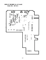
Page 31: ...CIRCUIT BOARD JU 475 4AGG Solder Side Bottom 29 ...
Page 34: ...Matsushita Communication industrial Co Ltd Memory Systems Division ...


