background image

PART.  I

1.  INTRODUCTION

This  service  manual  consists  o f  tw o   parts.  Part  I  covers  m aintenance  description,  adjustm ent 

procedures,  and  trouble  analysis  and  Part  II  covers  disassembly  and  reassembly  procedures,  parts 
list, and  PCB circuits.
Part  I  encompasses  maintenance  instructions fo r all  Floppy  Disk  Drive  (FDD)  models.  Refer to  the 
highlighted applicable items, and perform  maintenance w o rk on the FDD.

Note  : 

This service manuals is prepared fo r maintenance o f the FDD.

Do not use this manual fo rju d g in g  pass or fa il criteria in inspections.

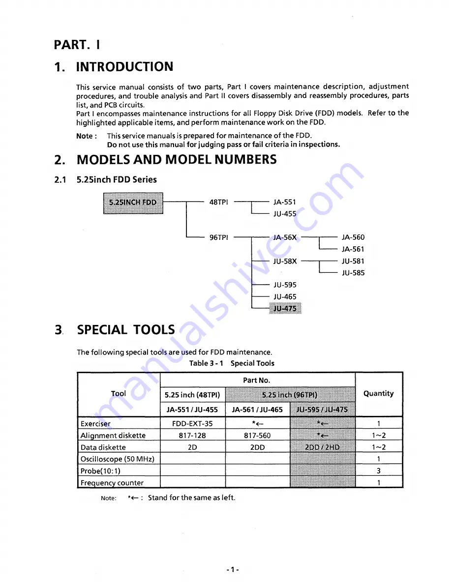
2.  MODELS AND  MODEL NUMBERS

2.1 

5.25inch FDD Series

5

,

25

INCH FDD

48TPI

96TPI

SPECIAL  TOOLS

JA-551

JU-455

JA-56X

JU-58X

JU-595

JU-465

J IM 7 5

JA-560

JA-561

JU-581

JU-585

The fo llo w in g  special tools are used fo r FDD maintenance.

Table 3 -1   Special Tools

Tool

Part No.

Q uantity

5.25 inch (48TPI)

5.25 inch (96TPI)

JA-551/JU-455

JA-561  /JU-465

JU-595 /JU-475

Exerciser

FDD-EXT-35

*< -

1

A lig nm en t diskette

817-128

817-560

*(fr~

1 ~ 2

Data diskette

2D

2DD

2D D /2H D

1 ~2

Oscilloscope (50 MHz)

1

Probe(10:1)

3

Frequency counter

1

Note: 

*«-  :  Stand fo r the same as left.

Summary of Contents for JU-475-4

Page 1: ...ORDER NO MSD891122000 Service Manual Flexible Disk Storage Drive JU 475 4 Panasonic ...

Page 2: ...k 0 Sensor Adjustment 10 9 10 Asymmetry Verification 11 10 TEST PO IN TS 12 11 PANASONIC ALIGNMENT DISKETTE 13 PART II 12 REMOVALS AND INSTALLATIONS 14 12 1 PCB Removal and Installation 14 12 2 Front Plate and Handle Removal and Installation 14 12 3 Track 0 Sensor Removal and Installation 15 12 4 Collet Assembly Removal Installation and Adjustment 15 12 5 Clamp Assembly Removal and Installation 16...

Page 3: ...d for maintenance of the FDD Do not use this manual forjudging pass or fail criteria in inspections 2 MODELS AND MODEL NUMBERS 2 1 5 25inch FDD Series 5 25INCH FDD 48TPI 96TPI 3 SPECIAL TOOLS JA 551 JU 455 JA 56X JU 58X JU 595 JU 465 JIM 75 JA 560 JA 561 JU 581 JU 585 The following special tools are used for FDD maintenance Table 3 1 Special Tools Tool Part No Quantity 5 25 inch 48TPI 5 25 inch 96...

Page 4: ...s kind of contamination can be easily eliminated by the liner in the diskette Please follow the appropriate procedures provided w ith the cleaning diskette 2 Random electrical noise normally a few microseconds or less 3 Small defects in written data and or track not detected during write operation may cause soft errors during read 4 Faulty grounding of the FDD or host system can also cause soft er...

Page 5: ...nment Refer to Adjustments and Confirmation section 9 6 2 Head output too low Refer to Confirmation section 9 3 3 Motor speed difference Refer to Adjustments and Confirmation section 9 1 4 Format incompatibility 6 TROUBLE ANALYSIS To determine the cause of trouble whether it lies in the FDD diskette or controller replace the diskette and the FDD with good ones If the FDD is assumed faulty as a res...

Page 6: ...6 2 Troubleshooting Flowchart Table6 1 Troubleshooting Flowchart 4 ...

Page 7: ...d load solenoid Replace u 4 PCB head load circuit Repair 5 No seek 1 Stepper motor Replace 2 Guide shaft contamination or damaqed Replace 3 PCB stepper driver circuit Repair 6 No write 1 See Item 1 2 See Item 4 3 Head disconnected l i i i i i i i i i i i 4 Head shorted Replace 5 Head load bail height wrong Adjustable 6 PCB write circuit Repair 7 No read 1 See Item 1 2 See Item 4 3 See Item 6 4 PCB...

Page 8: ...a mode MAXI mode TRACK VALUE TRACK v a lu e 1 Index period 32 2ÖÖ 3 0ms 32 166 7 3 4rrts 2 Output level 79 18QmV or more 79 IBOmVor more 3 Modulation 00 79 20 or less O O 79 20 or less 4 Resolution 79 60 or more 7 9 60 or more 5 Radial Aliqnment 32 70 6 Azimuth 1 i i i i l l l l l l 7 Index burst 68 250 I50us 8 Track 0 From track 0 to track 2 and back Q 6xVrc TH S 9m 8 ll l l l i8 lll ll 9 Asymmet...

Page 9: ... Diskette w ith write protect hole closed OFF ON Not write protected w rite protected 9 3 Head Output Verification Use a new diskette if possible to identify head failure for this check 1 Insert a good diskette 2 Run the motor 3 Step to the track specified in the output level column of Table 8 1 4 Connect the oscilloscope probe as specified below CHI CH2 EXT TP1 TP2 TP7 Invert channel 2 and select...

Page 10: ... for the stepper motor loosen or if parts become defective or if a compatibility error occurs check and readjust according to the following procedure Steps 4 to 9 below should be performed regardless of the type CE or DAD alignment diskette used Use an alignment diskette suitable to the type of FDD to be adjusted according to Table 3 1 1 Insert Panasonic alignment diskette CAUTION Be sure to leave...

Page 11: ...cifications of Table 8 1 when A B x 100 when A B x 100 Fig 9 2 Radial Alignment Waveforms CATS EYE Fig 9 2 1 Stepper M otor Mounting Screws 1 1 A fit11 ifjijJ H 1 1 1 t f i titl l itufi f m ll 1 9 7 Azimuth Verification 1 Insert an alignment diskette Seek to the track specified in the azimuth column of Table 8 1 2 Set the oscilloscope in the same conditions as in section 9 3 and set horizontal def...

Page 12: ...fications are not met adjust as follows Loosen the index detector mounting screws enough to free the assembly Adjust the tim ing to meet the specifications of Table 8 1 Retighten the screw Check the tim ing again 9 9 Track 0 Sensor Adjustment 1 Set the oscilloscope as follows TRIG SYNC CHI CH2 VERT HORIZ INT i l l TP12 TP 8 0 2V 1 ms 2 Step between specified tracks at in the track 0 item of Table ...

Page 13: ...asymmetry item of Table 8 1 3 Set the oscilloscope as follows TRIG SYNC CH 1 CH 2 VERT HORIZ INT 1 1 1 I I I TP 1 0 1 V I jjiS 4 W rite 1F 5 A read waveform is displayed on the oscilloscope as shown in Fig 9 7 6 Confirm if it satisfies the value as shown in Fig 8 1 Fig 9 7 Asymmetry Waveform ...

Page 14: ...10 TEST POINTS Printed Circuit Board Top View GND Vout Vout GND TRK0 TP 8 kJ 1 2 ...

Page 15: ...IC ALIGNMENT DISKETTE Table 10 1 Panasonic Alignment Diskette TPI Part No Index Burst Azimuth Radial Alignment Model 48 817 128 34TRK 34TRK 16TRK JA 551 JU 455 817 560 68TRK 68TRK 32TRK JA 561 JÜ 465 JU 95 JU 475 ...

Page 16: ...t0 the rib projected on the base The cable shall not protrude above the upper face of the drive Make it flat by pressing with a finger Do not damage or disconnect the pig tail by pressing it forcibly into the much in the PCB Fig 12 1 2 Cable Leading 12 2 Front Plate and Handle Removal and Installation 1 Operate the lock cam of the clamp assembly and turn the clamp handle in the direction of clampi...

Page 17: ...k 0 Sensor Assembly Removal 12 4 Collet Assembly Removal Installation and Adjustment 1 Remove the cartridge guide assembly as described in section 12 7 2 Remove the lifter unit as described in section 12 12 3 Remove the collet assembly from the guide shaft 4 Reverse the above procedure to reinstall 5 After reinstallation perform collet assembly center adjustment 6 Collet assembly center adjustment...

Page 18: ...e pins w ith lifting the stopper on the connector 4 Draw out the pins of the index sensor assembly from the following locations on the J3 connector No5 7 At that time draw out the pins w ith lifting the stopper on the connector 5 Remove the write protect sensor mounting screw and index sensor mounting screw respectively 6 Reverse the above procedure to reinstall 7 When reinstalling the w rite prot...

Page 19: ... the three cartridge guide mounting screws and take out the cartridge guide assembly 6 After reinstallation adjust the collet assembly as in section 12 4 step 6 and adjust the index burst as in section 9 8 7 When removing or reinstalling be careful not to damage the carriage arm w ith the lifter 12 7 Cartridge Guide Assembly Removal and Installation 1 7 Fig 12 6 W rite Protect Sensor Assembly and ...

Page 20: ...he radial alignment and track 0 sensor as described in section 9 6 and 9 9 Stepper Motor Assembly Fig 12 8 Stepper Motor Assembly Removal 1 Remove the PCB as described in section 12 1 2 Remove the one pig tail clamp mounting screw 3 Remove the tw o guide rod clamp mounting screws 4 Remove the head carriage assembly guide rod clamp guide rod and pig tail clamp 5 Pull out the guide rod from the head...

Page 21: ...ontact w ith the inner wall of the base Contacting of the pig tail is allowable if the side 0 and side 1 are not overlapped each other vertically 4 Fig 12 9 2 When the carriage is on the inner most track a When the head carriage is on the inner most track lead the side 0 and side 1 along line B on the pig tail clamp 5 Provide a clearance of about 1mm between the side 0 and side 1 6 Ensure that the...

Page 22: ...k C Provide a clearance of about 1 mm between the Side 0 and Side 1 approximately within this range Align the center with line B 1 Remove the cartridge guide assembly as described in section 12 7 2 Remove the three drive m o tor m ounting screws and take off the drive motor from the base 3 Reverse the above procedure to reinstall 4 After reinstallation the adjustments necessary upon reinstallation...

Page 23: ... from PCB 3 Remove the LED assembly by sliding it slant from the cartridge guide assembly 4 Reverse the above procedure to reinstall 5 The LED can be removed and installed as it is 1 Remove the clamp assembly as described in section 12 5 2 Remove the lifter shaft clamping retaining ring and draw out the lifter shaft 3 Remove the lifter unit 4 Reverse the above procedure to reinstall 21 ...

Page 24: ...escribed in section 12 1 2 Remove the cartridge guide assembly as described in section 12 7 3 Draw out the pins of the media sensor assembly from the fo llo w in g locations on th e J3 connector No8 10 12 A t that time draw out the pins w ith lifting the stopper on the connector 4 Remove the media sensor assembly mounting screw and take out the media sensor assembly 5 Reverse the above procedure t...

Page 25: ...13 EXPLODED VIEW JU 475 4AGG Caution For transportation insert the dummy diskette in the drive unit and close the lever Remove the dummy diskette before use of the drive unit 23 ...

Page 26: ...ex Sensor 2 18 YTF3L12930B2 Base 1 19 YTUF5DMT 3BT Drive M otor FMD01732B4T 1 2 20 YTF1G01482B3 Pig Tail Clamp 1 22 YTF7K14480B4 LED Holder Assembly 1 23 YTF3C07194B3 Lifter 1 24 YTF3C10760B3 Media Lifter 1 25 YTF4H01360B4 Lift Shaft 2 26 YTF4H03109B3 Clamp Cam Assembly 1 27 YTF4J01901B4 Lift Spring 1 28 YTF4J03500B4 Media Lift Spring 1 29 YTUF52CLT Collet Assembly 1 2 30 YTUF45WP8 Write Protect S...

Page 27: ...25 26 MCH212F104ZK Chip Capacitor 2 C27 ECEA1EKS330E Electrolyte Capacitor 1 C28 MCH212F104ZK Chip Capacitor 1 C29 ECEA1EKS330E Electrolyte Capacitor 1 C30 MCH212F104ZK Chip Capacitor 1 C31 ECEA1EKS330E Electrolyte Capacitor 1 C32 MCH215F103ZK Chip Capacitor 1 C34 MCH212F104ZK Chip Capacitor 1 D1 MA151WK TX Diode 1 D2 3 MA122 TX Diode 2 D4 MA121 TX Diode 1 D8 9 DA116 T96 Diode 2 D12 13 MAI 57 TX D...

Page 28: ...EYG203V Chip Resistor 1 R32 ERJ6GEYG363V Chip Resistor 1 R33 ERJ6GEYG203V Chip Resistor 1 R34 ERJ6GEYG363V Chip Resistor 1 R35 ERJ6GEYG203V Chip Resistor 1 R36 ERJ6GEYJ392V Chip Resistor 1 R37 39 ERJ6GEYJ102V Chip Resistor 3 R40 ERJ6GEYJ163V Chip Resistor 1 R41 42 ERJ6GEYJ362V Chip Resistor 2 R43 ERG1SJ271V Metal Film Oxide Resistor 1 R44 ERG1SJ151V Metal Film Oxide Resistor 1 R45 ERJ6GEYJ104V Chi...

Page 29: ...R ÖN DIRECTION SELECT S T E P WRITE DATA WRITE GATE SID E SELECT IN U S E H E A D LOAD SIDED R W 2 CÖM L2 FERRITE 5v o c m S f l C3 I 0 5 V C2 33JJ 25 V WRITE PROTECT PC WRITE PROTECT PE INDEX PE INDEX PC TRACK 0 0 PC TRACK 0 0 PE TRACK 00 LA MEDIA SENSOR PC MEDIA SENSOR PE MEDIA SENSÖR LA NOT INSTALLED 1Kn x 6 n r 2 7 ...

Page 30: ...17 CIRCUIT BOARD JU 475 4AGG Component Side Top 28 TP5 L 6 ...

Page 31: ...CIRCUIT BOARD JU 475 4AGG Solder Side Bottom 29 ...

Page 32: ... 3 0 MEDIA DETECTOR TRACK 00 DETECTOR HEAD Side 0 HEAD Side 1 WRITE PROTECT DETECTOR J3 1 GND 3 5 R W 1 7 COM 9 R W 2 11 ERASE 2 L ERASE 6 R W 2 8 COM 10 R W 1 12 GND J4 J2 TO HOST POWER SUPPLY ...

Page 33: ... USE 4 DRIVE SELECT 4 6 INDEX 8 DRIVE SELECT 1 10 DRIVE SELECT 2 12 DRIVE SELECT 3 14 MOTOR ON 16 DIRECTION SELECT 18 STEP 20 WRITE DATA 22 WRITE GATE 24 TRACK 00 26 WRITE PROTECT 28 READ DATA 30 SIDE SELECT 32 READY DRIVE STATUS 34 1 33 odd number SIGNAL GND TO HOST SIGNAL 18 BLOCK DIAGRAM ju 475 4 ...

Page 34: ...Matsushita Communication industrial Co Ltd Memory Systems Division ...

Reviews: