13
Icon
Function
1
~
16
ALARM1
~
ALARM16. The alarm becomes activated in the
low level.
NO1 C1
,
NO2 C2
Two NO activation output groups. (On-off button).
NO3 C3 NC3
One NO/NC activation output group. (On-off button).
CTRL 12V
Control power output. Disable power output when alarm is
canceled. Current is 500mA.
+12V
Rated current output. Current is 500mA.
GND
A/B
485 communication port. They are used to control devices
such as PTZ. Please parallel connect 120TΩ between A/B
cables if there are too many PTZ decoders.
2.3.2
Alarm input port
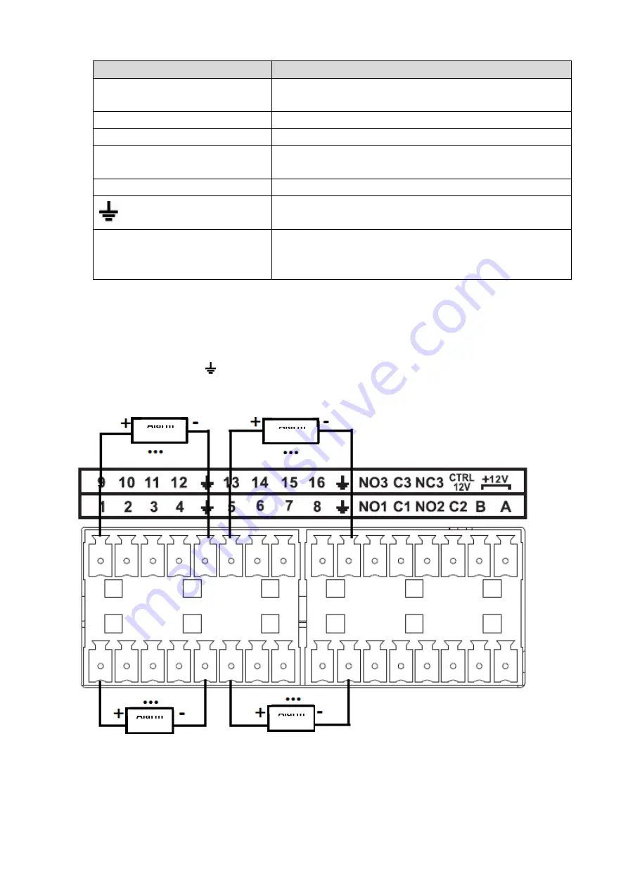
Connect the positive end (+) of the alarm input device to the alarm input port (ALARM IN 1
~
4(K-NL304K,
K-NL308K), ALARM IN 1
~
16 (K-NL316K)) of the NVR. Connect the negative end (-) of the alarm input
device to the ground end ( ) of the NVR.
The K-NL316K alarm input port is shown as below. See Figure 2-8
Figure 2-8
Alarm
Device
Alarm
Device
Alarm
Device
Alarm
Device
Summary of Contents for k-nl304k
Page 1: ...Network Disk Recorder User s Manual Model No K NL304K K NL308K K NL316K Version 1 0 5 ...
Page 32: ...23 The following figure is based on our K NL316K product Figure 3 2 ...
Page 50: ...41 Figure 4 25 ...
Page 67: ...58 Figure 4 52 Figure 4 53 ...
Page 88: ...79 Figure 4 71 Figure 4 72 ...
Page 89: ...80 Figure 4 73 Figure 4 74 ...
Page 94: ...85 Figure 4 78 Figure 4 79 ...
Page 95: ...86 Figure 4 80 Figure 4 81 ...
Page 96: ...87 Figure 4 82 Figure 4 83 ...
Page 99: ...90 Figure 4 86 Figure 4 87 ...
Page 114: ...105 send rate and receive rate at the top panel Figure 4 105 ...
Page 119: ...110 Figure 4 111 Figure 4 112 ...
Page 129: ...120 Figure 4 125 Figure 4 126 ...
Page 164: ...155 Figure 5 38 Figure 5 39 Figure 5 40 ...
Page 172: ...163 Figure 5 51 Figure 5 52 Figure 5 53 Figure 5 54 ...


