57
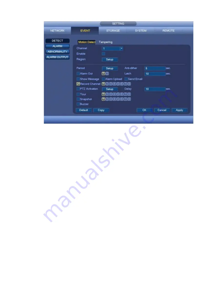
Figure 4-51
b) Select motion detect from the event type dropdown list. Select a channel from the dropdown list
and then check the enable box to enable motion detect function.
c) Click Region Setup button to set motion detect zone. There are 396(PAL)/330(NTSC) small
zones. The green zone is current cursor position. Grey zone is the motion detection zone. Black
zone is the disarmed zone. You can click FN button to switch between the arm mode and disarm
mode. In arm mode, you can click the direction buttons to move the green rectangle to set the
motion detection zone. After you completed the setup, please click ENTER button to exit current
setup. Do remember click save button to save current setup. If you click ESC button to exit the
region setup interface system will not save your zone setup.
d) Period: Click Setup button, you can see an interface is shown as in Figure 4-74. Here you can
set motion detect period. System only enables motion detect operation in the specified periods.
It is not for video loss or the tampering. There are two ways for you to set periods. Please note
system only supports 6 periods in one day.
e) Set sensitivity. Please note the sixth level has the highest sensitivity.
f) Click Save button to complete motion detect setup.
g) From Main menu->SETTING->STORAGE->SCHEDULE. See Figure 4-45
h) Set motion detect record channel, period and the record type shall be motion detect (MD).
Please refer to chapter 4.7.2.
i) Click Copy button to copy current setup to other channel(s).
j) Click OK button to complete motion detect record setup.
Summary of Contents for k-nl308k
Page 1: ...Network Disk Recorder User s Manual Model No K NL304K K NL308K K NL316K Version 1 0 5 ...
Page 32: ...23 The following figure is based on our K NL316K product Figure 3 2 ...
Page 50: ...41 Figure 4 25 ...
Page 67: ...58 Figure 4 52 Figure 4 53 ...
Page 88: ...79 Figure 4 71 Figure 4 72 ...
Page 89: ...80 Figure 4 73 Figure 4 74 ...
Page 94: ...85 Figure 4 78 Figure 4 79 ...
Page 95: ...86 Figure 4 80 Figure 4 81 ...
Page 96: ...87 Figure 4 82 Figure 4 83 ...
Page 99: ...90 Figure 4 86 Figure 4 87 ...
Page 114: ...105 send rate and receive rate at the top panel Figure 4 105 ...
Page 119: ...110 Figure 4 111 Figure 4 112 ...
Page 129: ...120 Figure 4 125 Figure 4 126 ...
Page 164: ...155 Figure 5 38 Figure 5 39 Figure 5 40 ...
Page 172: ...163 Figure 5 51 Figure 5 52 Figure 5 53 Figure 5 54 ...


