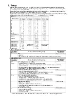
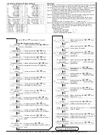

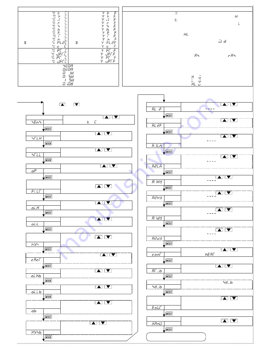
Press the
and
keys for approx. 3 seconds.
Scaling low limit
PV
SV
Set value
• Set the value with the
,
keys.
• Available for DC current, DC voltage input
Scaling high limit
PV
SV
Set value
• Set the value with the
,
keys.
• Available for DC current, DC voltage input
Decimal point place
PV
SV
Selection
• Make a selection with the
,
keys.
• Available for DC current, DC voltage input
PV filter time
constant
PV
SV
Set value
• Set the value with the
,
keys.
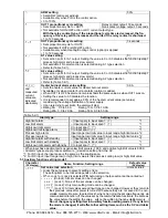
OUT1 low limit
PV
SV
Set value
• Set the value with the
,
keys.
• Not available for ON/OFF action
OUT1 high limit
PV
SV
Set value
• Set the value with the
,
keys.
• Not available for ON/OFF action
OUT1 ON/OFF action
hysteresis
PV
SV
Set value
• Set the value with the
,
keys.
• Available for ON/OFF action
OUT2 action mode
PV
SV
Selection
• Make a selection with the
,
keys.
• Available if Heat/Cool control (OUT2) is added
OUT2 high limit
PV
SV
Set value
• Set the value with the
,
keys.
• Available if Heat/Cool control (OUT2) is added
Overlap/Dead band
PV
SV
Set value
• Set the value with the
,
keys.
• Available only when Heat/Cool control (OUT2) is
added
OUT2 low limit
PV
SV
Set value
• Set the value with the
,
keys.
• Available if Heat/Cool control (OUT2) is added
OUT2 ON/OFF action
hysteresis
PV
SV
Set value
• Set the value with
,
keys.
• Available only when Heat/Cool control (OUT2) is
added
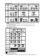
Input type
PV
SV
Selection
• Make a selection with the
,
keys.
• Default value:
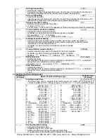
[Auxiliary function setting mode 2]
Output status selection
when input abnormal
PV
SV
Selection
• Make a selection with the
,
keys.
• Available only when input is DC current and DC
voltage with DC current output.
OUT/OFF key function
PV
SV
Selection
• Make a selection with the
,
keys.
Reverts to the PV/SV display.
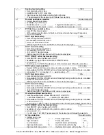
A1 type
PV
SV
Selection
• Make a selection with the
,
keys.
• Default value:
A1 hysteresis
PV
SV
Set value
• Set the value with the
,
keys.
• Not available if
is selected during A1
type selection
A2 type
PV
SV
Selection
• Make a selection with the
,
keys.
• Available when A2 is added
A1 action Energized/
Deenergized
PV
SV
Selection
• Make a selection with the
,
keys.
• Not available if
is selected during A1
type selection
A2 action Energized/
Deenergized
PV
SV
Selection
• Make a selection with the
,
keys.
• Not available if
is selected during A2
type selection
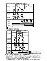
A1 action delayed
timer
PV
SV
Set value
• Set the value with the
,
keys.
• Not available if
is selected during A1
type selection
Direct/Reverse control
PV
SV
Selection
• Make a selection with the
,
keys.
• Default value:
A2 action delayed
timer
PV
SV
Set value
• Set the value with the
,
keys.
• Not available if
is selected during A2
type selection
A2 hysteresis
PV
SV
Set value
• Set the value with the
,
keys.
• Not available if
is selected during A2
type selection
AT bias
PV
SV
Set value
• Set the value with the
,
keys.
• Available for thermocouple, RTD input
(2)
Setting item not used
PV
SV
Set value
• Do not set this item even if
is indicated
on the PV display.
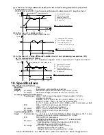
Input type (character indication) and range
K
–200 to 1370 :
–199.9 to 400.0 :
J
–200 to 1000 :
R
0 to 1760 :
S
0 to 1760 :
B
0 to 1820 :
E
–200 to 800 :
T
–199.9 to 400.0 :
N
–200 to 1300 :
PL-
0 to 1390 :
C(W/Re5-26) 0 to 2315 :
K –320 to 2500 :
–199.9 to 750.0 :
J –320 to 1800 :
R 0 to 3200 :
S 0 to 3200 :
B 0 to 3300 :
E –320 to 1500 :
T –199.9 to 750.0 :
N –320 to 2300 :
PL- 0 to 2500 :
C
(W/Re5-26)
0 to 4200
:
Pt100 –199.9 to 850.0 :
JPt100 –199.9 to 500.0
:
Pt100 –200 to 850 :
JPt100 –200 to 500 :
Pt100 –199.9 to 999.9
:
JPt100 –199.9 to 900.0 :
Pt100 –30 0 to 1500 :
JPt100 –300 to 900 :
4 to 20mA DC –1999 to 9999:
0 to 20mA DC –1999 to 9999:
0 to 1V DC
–1999 to 9999:
0 to 5V DC –1999 to 9999:
1 to 5V DC –1999 to 9999:
0 to 10V DC –1999 to 9999:
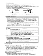
Alarm type
High limit alarm: The alarm action is deviation setting from the SV. The alarm is activated
if the input value reaches the high limit set value. Character indication:
Low limit alarm: The alarm action is deviation setting from the SV. The alarm is activated
if the input value goes under the low limit set value. Character indication:
High/Low limits alarm: Combines High limit and Low limit alarm actions. When input value
reaches high limit set value or goes under the low limit set value, the alarm
is activated. Character indication:
High/Low limit range alarm: When input value is between the high limit set value and low
limit set value, the alarm is activated. Character indication:
Process alarm: Within the scale range of the controller, alarm action points can be set
at random and if the input reaches the randomly set action point, the alarm is
activated.
Character indication: Process high alarm
, Process low alarm
Alarm with standby function: When the power to the controller is turned on, even if the input
enters the alarm action range, the alarm is not activated. (If the controller is
allowed to keep running, once the input exceeds the alarm action point, the
standby function will be released.)
Character indication:
High limit alarm with standby
:
Low limit alarm with standby
:
High/Low limits alarm with standby :
(1)
(3)
(4)
Press the
and
keys for approx. 3 seconds.
Phone: 800.894.0412 - Fax: 888.723.4773 - Web: www.clrwtr.com - Email: info@clrwtr.com


