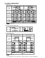

8.4 A1 and A2 action
A1 indicator lights when its output terminals 3 and 4 are connected (ON), and goes off when
they are not connected (OFF).
A2 indicator lights when its output terminals 3 and 5 are connected (ON), and goes off when
they are not connected (OFF).
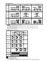
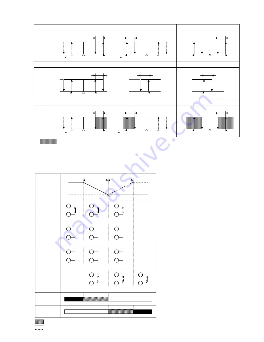
8.5 Heating/Cooling control action
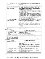
High limit alarm
Alarm
action
High/Low limits alarm
Low limit alarm
OFF
ON
A1 hysteresis
OFF
ON
SV
setting
A1 set point
OFF
ON
A1 hysteresis
A1 hysteresis
A1 set point
SV
setting
+ A1 set point
A1 set point
A1 set point
SV
setting
+ A1 set point
High/Low limit range alarm
Process high alarm
Process low alarm
OFF
ON
OFF
ON
OFF
ON
Alarm
action
A1 hysteresis
A1 hysteresis
A1 hysteresis
A1 set point
A1 set point
A1 set point
A1 set point
SV
setting
High limit alarm with standby
High/Low limit alarm with standby
Low limit alarm with standby
OFF
ON
OFF
ON
OFF
ON
Alarm
action
A1 hysteresis
A1 hysteresis
A1 hysteresis
A1 set point
A1 set point
SV
setting
SV
setting
+ A1 set point
A1 set point
A1 set point
SV
setting
+ A1 set point
: Standby functions in this section.
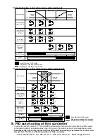
Cycle action is performed according to deviation.
OFF
ON
SV setting
OFF
ON
7
7
7
6
6
6
6
+
7
-
12V DC
6
+
7
-
12/0V DC
6
+
7
-
0V DC
6
+
7
-
20mA DC
6
+
7
-
20 to 4mA DC
6
+
7
-
4mA DC
3
3
3
5
5
5
Heating
action
(Cooling
action)
Heating P-band
(Cooling P-band)
Cycle action is performed according to deviation.
Changes continuously according to deviation.
Control action
Relay contact
output (OUT1)
Non-contact
voltage output
(OUT1)
DC current
output (OUT1)
Non-contact
relay output
(OUT2)
Indicator
(OUT1) Green
Indicator
(OUT2) Yellow
Lit
Unlit
Lit
: Acts ON (lit) or OFF (unlit).
: Represents Heating control action.
: Represents Cooling control action.
Unlit
Cycle action is performed according to deviation.
Phone: 800.894.0412 - Fax: 888.723.4773 - Web: www.clrwtr.com - Email: info@clrwtr.com


