51
(2) Error check of RTU mode
After calculating CRC-16 (Cyclic Redundancy Check) from the slave address to the end of data, the
calculated 16-bit data is appended to the end of message in sequence from low order to high order.
How to calculate CRC
In the CRC system, the information is divided by the polynomial series. The remainder is added to the end
of the information and transmitted. The generation of polynomial series is as follows.
(Generation of polynomial series: X
16
+ X
15
+ X
2
+ 1)
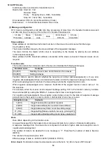
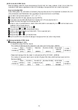
1
Initialize the CRC-16 data (assumed as X) (FFFFH).
2
Calculate exclusive OR (XOR) with the 1st data and X. This is assumed as X.
3
Shift X one bit to the right. This is assumed as X.
4
When a carry is generated as a result of the shift, XOR is calculated by X of
3
and the fixed value
(A001H). This is assumed as X.
If a carry is not generated, go to step
5
.
5
Repeat steps
3
and
4
until shifting 8 times.
6
XOR is calculated with the next data and X. This is assumed as X.
7
Repeat steps
3
to
5
.
8
Repeat steps
3
to
5
up to the last data.
9
Set X as CRC-16 to the end of message in sequence from low order to high order.
(3) Message example of RTU mode
1
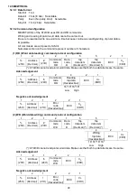
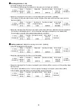
Reading (Address 1, PV)
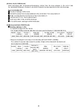
• A request message from the master
The number of data means the data item to be read, and it is fixed as 1 (0001H).
3.5 idle
characters
Slave
address
(01H)
Function
code
(03H)
Data item
(0080H)
Number of data
(0001H)
Error check
CRC-16
(85E2H)
3.5 idle
characters
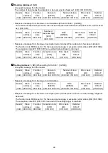
• Response message from the slave in normal status (When PV=600
[0258H])
The number of response byte means number of bytes of the data which has been read, and it is
fixed as 2 (02H).
3.5 idle
characters
Slave
address
(01H)
Function
code
(03H)
Number of
response byte
(02H)
Number of data
(0258H)
Error check
CRC-16
(B8DEH)
3.5 idle
characters

