6
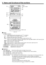
2. Name and functions of the sections
Bottom view
(Fig. 2-1)
Display
(1)
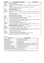
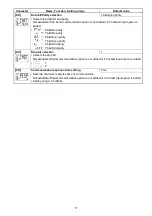
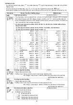
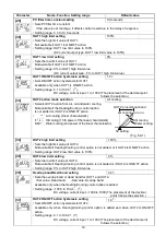
Action indicators
: Lights respectively when temperature unit
/
is selected.
T/R
: Lights during Serial communication (optional) TX output.
AT
: Flashes during auto-tuning or auto-reset.
OUT1
: Lights when control output is ON or Heating output (optional) is ON.
For DC current output type, it flashes corresponding to the manipulated variable in 0.25 second cycles.
OUT2
: Lights when Cooling output (optional) is ON.
EVT1
: Lights when Alarm 1 output is ON.
EVT2
: Lights when Alarm 2 output (optional) is ON or Heater burnout alarm (optional) is ON.
LOCK
: Lights when Lock 1, Lock 2 or Lock 3 is selected.
(2)
MEMO display
: Indicates the set value memory number.
(3)
PV display
: Indicates the PV (process variable).
(4)
SV display
: Indicates the SV (set value).
Operations
(5)
Mode key
: Selects the setting mode, and registers the set value.
(6)
OUT/OFF key
: The control output ON/OFF or Auto/Manual control can be switched.
(7)
Increase key
: Increases the numeric value.
(8)
Decrease key
: Decreases the numeric value.
(9)
Tool connector
: By connecting the tool cable (AKT4H820, sold separately), the following operations can
be conducted from the external computer using the exclusive tool software.
(1) Reading and setting of SV, PID and various set values from external computer
(2) Reading of PV and action status
(3) Function change
Cannot be used with Serial communication option.
Please download the exclusive tool software from our website.
(9)
(1)
(2)
(3)
(4)
(5)
(6)
(7)
(8)
Model
KT4H or KT4B


