15
10. PID auto-tuning of this controller
In order to decide each value of P, I, D and ARW automatically, the auto-tuning process should be
made to fluctuate to obtain an optimal value.
Sometimes the auto-tuning process will not fluctuate if auto-tuning is performed at or near
room temperature. Therefore auto-tuning might not finish normally.
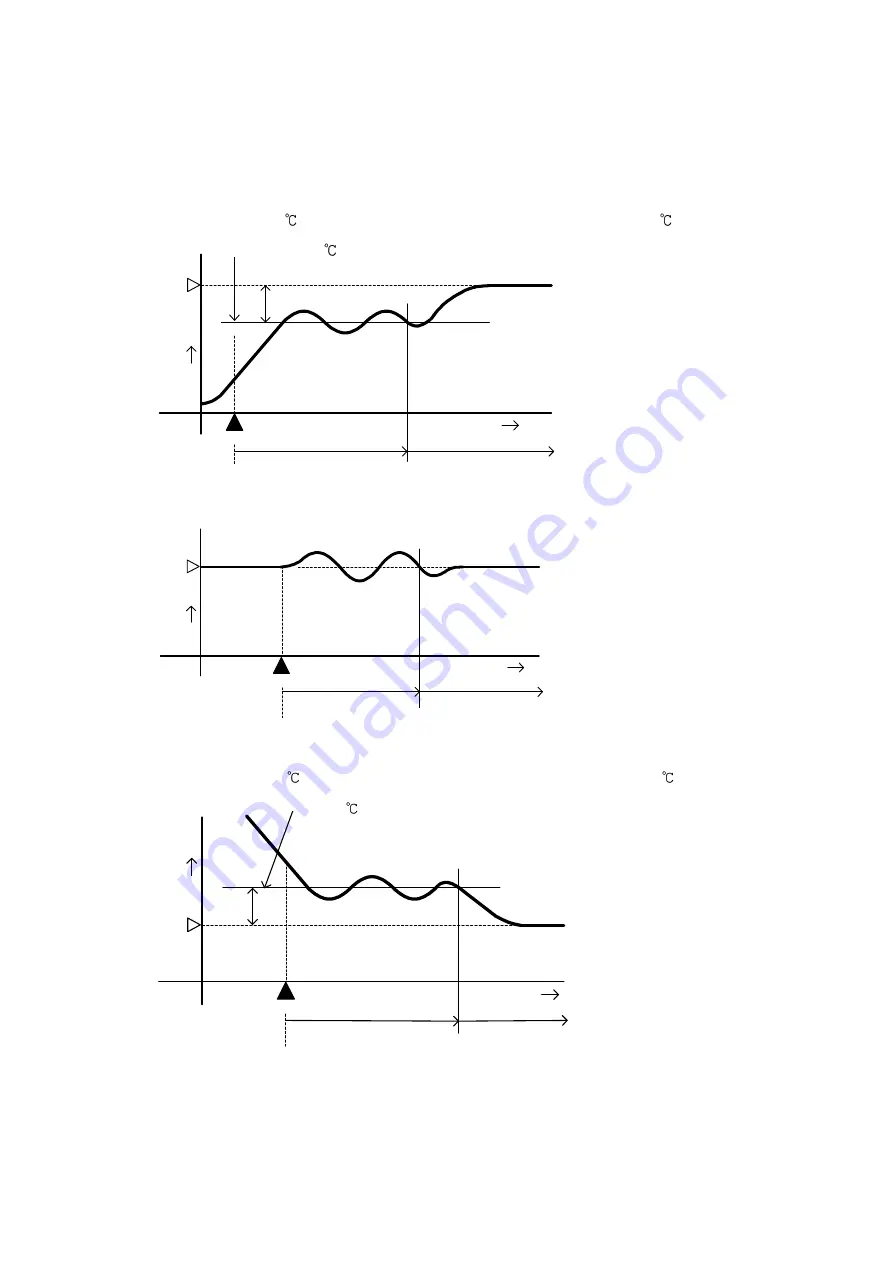
(A) In the case of a large difference between the SV and processing temperature as the
temperature is rising
When AT bias is set to
20 , the AT process will fluctuate at the temperature 20
lower than the SV.
Temperature 20
lower than the SV
(1) Calculating PID constant
(2) PID constant calculated
(3) Controlled by the PID
constant set by auto-tuning
(4) AT bias value
(B) When control is stable
The AT process will fluctuate around the SV.
(1) Calculating PID constant
(2) PID constant calculated
(3) Controlled by the PID
constant set by auto-tuning
(C) In the case of a large difference between the SV and processing temperature as the
temperature is falling
When AT bias is set to
20 , the AT process will fluctuate at the temperature 20
higher than the SV.
Temperature 20
higher than the SV
(1) Calculating PID constant
(2) PID constant calculated
(3) Controlled by the PID
constant set by auto-tuning
(4) AT bias value
11. Specifications
11.1 Standard specifications
Model
: Temperature controller
Mounting
: DIN rail mounting
Setting
: Input system using membrane sheet key
Display
PV display
: Red LED 4 digits, character size 7.4 x 4mm (H x W)
SV display
: Green LED 4 digits, character size 7.4 x 4mm (H x W)
(1)
(2)
(3)
(4)
AT starting point
SV
Temperature
Time
AT starting point
(1)
(2)
(3)
Temperature
SV
Time
AT starting point
(1)
(2)
(3)
(4)
Temperature
SV
Time
(Fig. 10-1)
(Fig. 10-2)
(Fig. 10-3)

