9
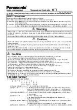
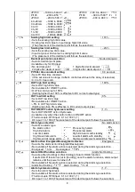
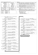
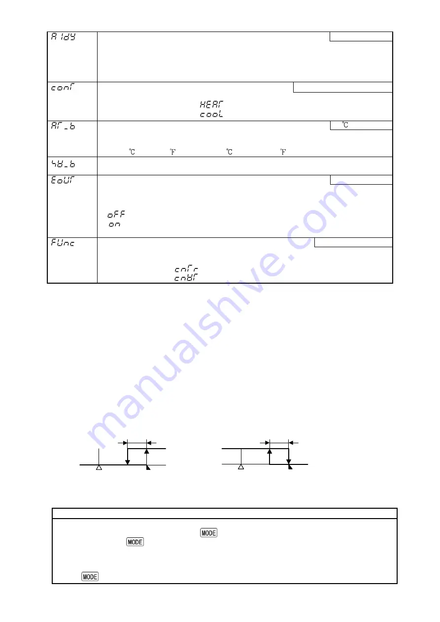
Alarm action delayed timer setting
0 seconds
• Sets the alarm action delayed time.
When the setting time has passed after the input enters alarm output range, the
alarm is activated.
• Not available if No alarm action is selected during the Alarm type selection.
• 0 to 9999 seconds
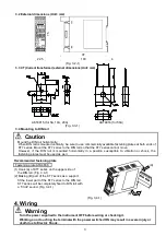
Direct/Reverse control action selection
Reverse (Heating) action
• Selects either Reverse (Heating) or Direct (Cooling) control action.
• Reverse (Heating) action :
Direct (Cooling) action
:
AT bias setting
20
• Sets bias value during PID auto-tuning.
• Not available for the DC voltage or current input
• 0 to 50
(0 to 100 ) or 0.0 to 50.0
(0.0 to 100.0 )
Setting item not used
: This item is indicated when Serial communication (option) is
added. However, this cannot be used.
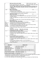
Output status selection when input abnormal
Output OFF
• Selects the output status of OUT when DC input is overscale or underscale.
See “Input abnormality indication” on page 18.
• Available only for DC current output with DC input
•
: OFF(4mA) or OUT low limit
: Outputs a value between OFF (4mA) and ON (20mA) or between OUT low
limit value and OUT high limit value, depending on a deviation.
Controller/Converter function selection
Controller function
• Selects either controller or converter function.
• Available only when the control output is DC current output type.
• Controller function:
Converter function:
ARW function
ARW (Anti-reset windup) prevents overshoot caused by the integral action. The smaller the ARW value, the less
the overshoot caused by the integral action in the transition status, however it takes time until stabilization.
Sensor correction function
This corrects the input value from the sensor. When a sensor cannot be set at a location where control
is desired, the sensor measuring temperature may deviate from the temperature in the controlled
location. When controlling with plural controllers, the accuracy of sensors affects the control. Therefore,
sometimes the measured temperatures (input value) do not concur.
In such a case, the control can be set at the desired temperature by adjusting the input value of sensors.
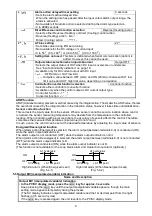
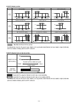
Energized/Deenergized function
When [alarm action Energized] is selected, the alarm output (between terminals 8-9) is conducted (ON)
while the alarm output indicator is lit.
The alarm output is not conducted (OFF) while the alarm output indicator is not lit.
When [alarm action Deenergized] is selected, the alarm output (between terminals 8-9) is not conducted
(OFF) while the alarm output indicator is lit.
The alarm output is conducted (ON) while the alarm output indicator is not lit.
[This function is not available for the Loop break alarm and Heater burnout alarm (optional).]
High limit alarm (When Energized is set)
High limit alarm (When Deenergized is set)
(Fig. 5.4-1)
(Fig. 5.4-2)
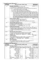
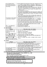
5.5 Output MV (manipulated variable) indication
Name and Description
Output MV (manipulated variable) indication
•
In the PV/SV display mode, press the
key for approx. 3 seconds.
Keep pressing the
key until the output manipulated variable appears, though the main
setting mode appears temporarily during the process.
(The SV display indicates output manipulated variable and the 1st decimal point from the right
flashes in 0.5 second cycles)
If the
key is pressed again, the unit reverts to the PV/SV display mode.
OFF
ON
A1 hysteresis
SV setting
+ A1 set point
OFF
ON
SV setting
+ A1 set point
A1 hysteresis

