15
5. Setup
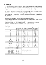
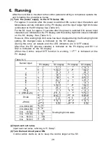
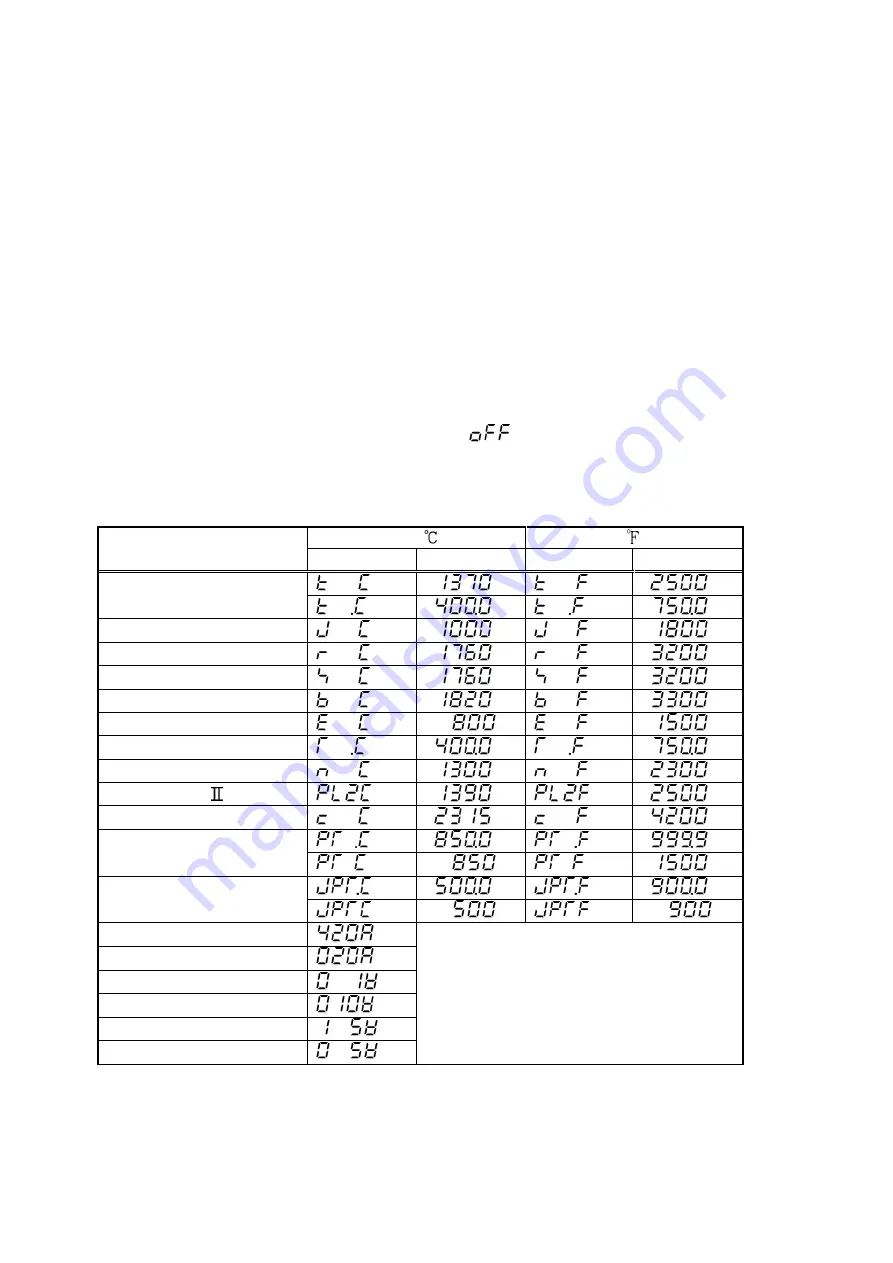
For the thermocouple and RTD input, the sensor input characters and temperature unit
are indicated on the PV display and the input range high limit value is indicated on the SV
display for approx. 3 seconds after the power is turned on. See (Table 5-1).
For DC input, the sensor input characters are indicated on the PV display and the scaling
high limit value is indicated on the SV display. See (Table 5-1).
If any other value is set during the scaling high limit setting, the set value is indicated on
the SV display.
During this time, all outputs and the LED indicators are in OFF status.
Control will then start and the PV (process variable) will be indicated on the PV display
and SV1 or SV2 will be indicated on the SV display.
While control output OFF function is working,
is indicated on the PV display.
To release the function, press the OUT/OFF key for approx. 1 second.
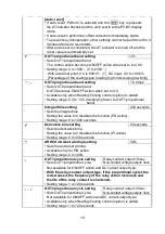
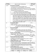
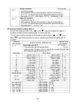
(Table 5-1)
Sensor input
PV display
SV display
PV display
SV display
K
J
R
S
B
E
T
N
PL-
C (W/Re5-26)
Pt100
JPt100
4 to 20mA DC
0 to 20mA DC
0 to
1V DC
0 to 10V DC
1 to
5V DC
0 to
5V DC
Scaling high limit value

