background image

36

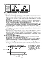
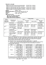
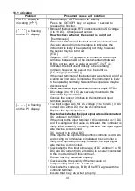
(B) In the case of a stable control

The AT process will fluctuate around the SV.

(1) Calculating PID constant
(2) PID constant calculated
(3) Controlled by the PID

constant set by auto-tuning

(Fig. 8.2-2)

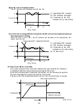
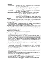
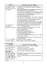
(C) In the case of a large difference between the SV and processing temperature as

the temperature is falling

When AT bias is set to 20 , the

AT process will fluctuate

at the temperature 20

higher than the SV.

(1) Calculating PID constant
(2) PID constant calculated
(3) Controlled by the PID

constant set by auto-tuning

(4) AT bias value

(Fig. 8.2.3)

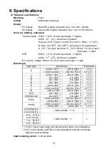
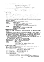
8.3 Auto-reset (offset correction)

Auto-reset is performed to correct the offset at the point at which PV indication
is stabilized within the proportional band during the PD action.
Since the corrected value is internally memorized, it is not necessary to perform
the auto-reset again as long as the process is the same.
However, when the proportional band is set to 0, the corrected value is cleared.

(Fig. 8.3-1)

Temperature

SV

Offset span

Time

Offset is corrected

Auto-reset is performed

AT starting point

(1)

(2)

(3)

Temperature

SV

Time

AT starting point

(1)

(2)

(3)

(4)

Temperature

SV

Time

Temperature 20

higher than the SV

Summary of Contents for KT9

Page 1: ...TEMPERATURE CONTROLLER KT9 INSTRUCTION MANUAL ...

Page 2: ...sures must be taken to ensure that the operator cannot touch power terminals or other high voltage sections Any unauthorized transfer or copying of this document in part or in whole is prohibited Panasonic Industrial Devices SUNX Co Ltd is not responsible for any damage or secondary damage s incurred as a result of using this product including any indirect damage To pull out the inner assembly rel...

Page 3: ...d from the left side The lead wire must be inserted from the left side of the terminal and fastened with the terminal screw Tighten the terminal screw within the specified torque If excessive force is applied to the screw when tightening the terminal screw or case may be damaged Do not apply a commercial power source to the sensor which is connected to the input terminal nor allow the power source...

Page 4: ...mode SV1 18 SV2 18 5 3 Output MV indication 18 5 4 Sub setting mode AT Auto reset 18 OUT1 proportional band 19 OUT2 proportional band 19 Integral time 19 Derivative time 19 ARW Anti reset windup 19 OUT1 proportional cycle 19 OUT2 proportional cycle 19 A1 value 20 A2 value 20 HB Heater burnout alarm value 20 5 5 Auxiliary function setting mode 1 Set value lock 21 SV high limit 21 SV low limit 21 Se...

Page 5: ...on 26 5 7 Control output OFF function 27 5 8 Auto Manual control 27 6 Running 28 7 Action explanation 7 1 OUT1 action 29 7 2 Heater burnout alarm action option 29 7 3 OUT1 ON OFF action 30 7 4 OUT2 Heating Cooling control action option 31 7 5 OUT2 Heating Cooling control action when setting Dead band 32 7 6 OUT2 Heating Cooling control action when setting Overlap band 33 7 7 A1 A2 action 34 7 8 SV...

Page 6: ...ontact 2 Non contact voltage Voltage output for SSR drive 3 DC current 4 Alarm output 1 A1 output 2 A1 output A2 output The alarm type and Energized Deenergized can be selected by keypad operation 5 Heating Cooling control OUT2 output 0 Not available 1 Relay contact 2 Non contact voltage 3 DC current 6 Heater burnout alarm 0 Not available 1 Available 5A 2 Available 10A 3 Available 20A 4 Available ...

Page 7: ...99 to 9999 1 2 1 0 to 20mA DC 1999 to 9999 1 2 1 0 to 1V DC 1999 to 9999 1 1 0 to 10V DC 1999 to 9999 1 1 1 to 5V DC 1999 to 9999 1 1 0 to 5V DC 1999 to 9999 1 1 1 For DC input the input range and decimal point place can be changed 2 For DC current input 50 shunt resistor AKT4810 sold separately must be connected between input terminals 1 3 How to read the rated label The rated label is attached t...

Page 8: ...t is on the green LED lights For the DC current output type this flashes corresponding to the output manipulated variable in 0 25 second cycles 6 OUT2 indicator When OUT2 is on the yellow LED lights For the DC current output type this flashes corresponding to the output manipulated variable in 0 25 second cycles 7 HB indicator When Heater burnout alarm output or sensor burnout alarm output is on t...

Page 9: ...n or off Once the control output OFF function is enabled the function cannot be released even if the power to the instrument is turned OFF and turned ON again To cancel the function press the OUT OFF key again for approx 1 second If Auto Manual control function is selected from OUT OFF function selection automatic control is performed when the power to the controller is turned on In this status if...

Page 10: ...0 to 50 32 to 122 that does not change rapidly 5 An ambient non condensing humidity of 35 to 85 RH 6 No large capacity electromagnetic switches or cables through which large current is flowing 7 No water oil or chemicals or where the vapors of these substances can come into direct contact with the unit 3 2 External dimensions Unit mm Fig 3 2 1 3 3 Panel cutout Unit mm Lateral close mounting n Numb...

Page 11: ...t or the case or screw type mounting bracket could be damaged The torque should be 0 12N m Mount the controller vertically to the flat rigid panel to ensure it adheres to the Dust proof Drip proof specification IP66 Mounting panel thickness 1 to 8mm Insert the instrument from the front side of the panel Attach the mounting bracket by the holes at the top and bottom of the case and secure in place ...

Page 12: ... turned on 4 1 Terminal arrangement OUT1 Control output 1 Heating output OUT2 Control output 2 Cooling output RELAY Relay contact output V A Non contact voltage output DC current output A1 Alarm 1 output A2 Alarm 2 output HB Heater burnout alarm output RS 485 Serial communication SV2 2nd SV CT CT input TC Thermocouple RTD Resistance temperature detector DC DC current or DC voltage For DC current i...

Page 13: ...f any other compensating lead wire is used a temperature indication error may be caused Use the 3 wire RTD according to the sensor input specifications of this controller This controller does not have built in power switch circuit breaker or fuse It is necessary to install them in the circuit externally near the controller Recommended fuse Time lag fuse rated voltage 250V AC rated current 2A For a...

Page 14: ...wires connected to the CT input terminals There is no polarity Fig 4 2 1 AKT9111100 Fig 4 2 2 To prevent the unit from harmful effects of unexpected high level noise it is recommended that a surge absorber be installed between the electromagnetic switch coils For a 24V AC DC power source do not confuse polarity when using direct current DC CT input terminals Power source CT Heater 15 16 3 phase El...

Page 15: ...uring the scaling high limit setting the set value is indicated on the SV display During this time all outputs and the LED indicators are in OFF status Control will then start and the PV process variable will be indicated on the PV display and SV1 or SV2 will be indicated on the SV display While control output OFF function is working is indicated on the PV display To release the function press the...

Page 16: ...F when set to 0 0 A2 value PV SV Set value Set the value with keys Not available if is selected during A2 type selection Reverts to the PV SV display Reverts to PV SV display Press the key Main setting mode Sub setting mode 5 PV SV display Control output OFF function or Auto Manual control function Press key for approx 1sec Output MV indication Explanation of key This means that if is pressed the ...

Page 17: ...g A1 type selection Direct Reverse control PV SV Selection Make a selection with the keys Default value A2 action delayed timer PV SV Set value Set the value with the keys Not available if is selected during A2 type selection A2 hysteresis PV SV Set value Set the value with the keys Not available if is selected during A2 type selection AT bias PV SV Set value Set the value with the keys Available ...

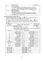
Page 18: ... by pressing the key while holding down the key The set value can be increased or decreased by pressing the or key The set value is registered by pressing the key then the next setting item is selected Character PV display Name Function Setting range Default value SV display AT setting Auto reset setting Cancel Sets AT auto tuning or Auto reset offset correction Auto reset can be performed only in...

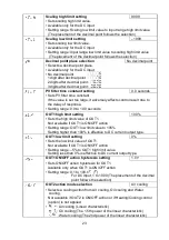
Page 19: ...tiplying factor to OUT1 proportional band Integral time setting 200 seconds Sets the integral time Setting the value to 0 disables the function PD action Setting range 0 to 1000 seconds Derivative time setting 50 seconds Sets the derivative time Setting the value to 0 disables the function PI action Setting range 0 to 300 seconds ARW Anti reset windup setting 50 Sets the anti reset windup Availabl...

Page 20: ... to 5 0A Rating 10A 0 0 to 10 0A Rating 20A 0 0 to 20 0A Rating 50A 0 0 to 50 0A Setting range of A1 and A2 Table 5 4 1 Alarm type Setting range High limit alarm Input span to input span 1 Low limit alarm Input span to input span 1 High Low limits alarm 0 to input span 1 High Low limit range alarm 0 to input span 1 Process high alarm Input range low limit to input range high limit 2 Process low al...

Page 21: ...70 Sets SV high limit Setting range SV low limit to input range high limit value DC input SV low limit to scaling high limit value The placement of the decimal point follows the selection SV low limit setting 200 Sets SV low limit Setting range Input range low limit value to SV high limit DC input Scaling low limit value to SV high limit The placement of the decimal point follows the selection Sen...

Page 22: ...istered and the next setting item is selected Character PV display Name Function Setting range Default value SV display Input type selection The input type can be selected from K 200 to 1370 thermocouple 10 types RTD 2 types DC current 2 types and DC voltage 4 types and the unit Input type Input range 200 to 1370 320 to 2500 K 199 9 to 400 0 199 9 to 750 0 J 200 to 1000 320 to 1800 R 0 to 1760 0 t...

Page 23: ...nse Setting range 0 0 to 10 0 seconds OUT1 high limit setting 100 Sets the high limit value of OUT1 Not available if OUT1 is ON OFF action Setting range OUT1 low limit value to 105 Setting higher than 100 is effective to DC current output type OUT1 low limit setting 0 Sets the low limit value of OUT1 Not available if OUT1 is ON OFF action Setting range 5 to OUT1 high limit value Setting less than ...

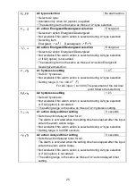
Page 24: ...value Dead band Set value Overlap band Not available if OUT2 is ON OFF action or if Heating Cooling control option is not applied Setting range 100 0 to 100 0 DC input 1000 to 1000 The placement of the decimal point follows the selection OUT2 ON OFF action hysteresis setting 1 0 Sets ON OFF action hysteresis for OUT2 Available when OUT2 is ON OFF action or when Heating Cooling control option is ap...

Page 25: ...ting range 0 1 to 100 0 For DC input 1 to 1000 The placement of the decimal point follows the selection A2 hysteresis setting 1 0 Sets A2 hysteresis Not available if No alarm action is selected during A2 type selection or if A2 option is not added The setting range is the same as those of A1 hysteresis setting A1 action delayed timer setting 0 seconds Sets the action delayed timer for A1 The Alarm...

Page 26: ...high limit value depending on a deviation OUT OFF key function selection Selects the OUT OFF key function OUT OFF function Selecting item OUT OFF function Auto Manual control function ARW function ARW Anti reset windup prevents overshoot caused by the integral action The smaller the ARW value the less the overshoot caused by the integral action in the transition status however it takes time until ...

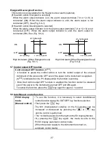
Page 27: ...ed instrument of the plural units OFF even if the power to the instrument is supplied is indicated on the PV display while the function is working Once the Control output OFF function is enabled the function cannot be released even if the power to the instrument is turned OFF and ON again To cancel the function press the key again for approx 1 second 5 8 Auto Manual control function PV SV display ...

Page 28: ...ee Table 6 1 However if the scaling high limit value has been changed during the Scaling high limit setting the changed value is indicated on the SV display During this time all outputs and the LED indicators are in OFF status After that the PV process variable is indicated on the PV display and SV1 or SV2 is indicated on the SV display When the Control output OFF function is working is indicated ...

Page 29: ... Cycle action is performed according to deviation Cycle action is performed according to deviation Changes continuously according to deviation OFF ON OFF ON 5 6 12V DC 5 6 12 0V DC 5 6 0V DC 5 6 0V DC 5 6 12V DC 5 6 0 12V DC 5 6 20mA DC 5 6 4mA DC 5 6 4mA DC 5 6 20mA DC 5 6 4 to 20mA DC 4 5 6 H C L 4 5 6 H C L 4 5 6 H C L 4 5 6 H C L 4 5 6 H C L 4 5 6 H C L 6 20 to 4mA DC 5 Cycle action is perform...

Page 30: ...ng OUT1 Green Indicator Unlit Hysteresis 5 6 12V DC 5 6 0V DC 5 6 0V DC 5 6 12V DC 5 6 20mA DC 5 6 4mA DC 5 6 4mA DC 5 6 20mA DC 4 5 6 H C L 4 5 6 H C L 4 5 6 H C L 4 5 6 H C L OFF ON OFF ON Lit Unlit Lit SV setting Relay contact output Non contact voltage output DC current output Acts ON lit or OFF unlit ...

Page 31: ...n is performed according to deviation Cycle action is performed according to deviation Cycle action is performed according to deviation Changes continuously according to deviation Cycle action is performed according to deviation Changes continuously according to deviation Lit Unlit Unlit Lit Indicator OUT1 Green Indicator Relay contact output OUT1 Relay contact output OUT2 Non contact voltage outp...

Page 32: ... SV setting Cycle action is performed according to deviation Cycle action is performed according to deviation Cycle action is performed according to deviation Cycle action is performed according to deviation Indication Indication Lit Unlit Lit Unlit Changes continuously according to deviation Changes continuously according to deviation Relay contact output OUT1 Relay contact output OUT2 Non contac...

Page 33: ...9 10 4mA DC 9 10 4 to 20mA DC 9 10 20mA DC Overlap band Heating action Cooling action Relay contact output OUT1 Relay contact output OUT2 OUT1 Green Indication OUT2 Yellow Indication Non contact voltage output OUT1 Unlit Lit Lit Unlit Changes continuously according to deviation Cycle action is performed according to deviation Cycle action is performed according to deviation Cycle action is perform...

Page 34: ...s alarm High Low limit range alarm A1 set point A1 set point A1 set point A1 set point A1 set point A1 set point A1 set point A1 set point A1 set point Alarm action Alarm action Alarm action High limit alarm with standby Low limit alarm with standby A1 set point SV setting A1 set point A1 set point A1 set point A1 set point A1 hysteresis A1 hysteresis A1 hysteresis A1 hysteresis A1 hysteresis A1 h...

Page 35: ... is also accelerated and the control becomes unstable 3 Derivative time D Derivative action is used to restore the change in the processing temperature according to the rate of change It reduces the amplitude of overshoot and undershoot width If the derivative time is shortened restoring value becomes small and if the derivative time is extended an excessive returning phenomenon may occur and the ...

Page 36: ...by the PID constant set by auto tuning 4 AT bias value Fig 8 2 3 8 3 Auto reset offset correction Auto reset is performed to correct the offset at the point at which PV indication is stabilized within the proportional band during the PD action Since the corrected value is internally memorized it is not necessary to perform the auto reset again as long as the process is the same However when the pr...

Page 37: ...0 2 of each input span 1digit Rated input Input type Input range Resolution 200 to 1370 320 to 2500 1 K 199 9 to 400 0 199 9 to 750 0 0 1 J 200 to 1000 320 to 1800 1 R 0 to 1760 0 to 3200 1 S 0 to 1760 0 to 3200 1 B 0 to 1820 0 to 3300 1 E 200 to 800 320 to 1500 1 T 199 9 to 400 0 199 9 to 750 0 0 1 N 200 to 1300 320 to 2300 1 PL 0 to 1390 0 to 2500 1 C W Re5 26 0 to 2315 0 to 4200 1 199 9 to 850 ...

Page 38: ...ad cosø 0 4 Electrical life 100 000 cycles Non contact voltage 12 2 0V DC maximum 40mA short circuit protected DC current 4 to 20mA DC Load resistance maximum 550 A1 output When A1 action is set as Energized the alarm action point is set by deviation from the SV except Process alarm When the input is out of the range the output turns ON or OFF in the case of High Low limit range alarm When the ala...

Page 39: ...40V AC 50 60Hz 24V AC DC 50 60Hz Allowable voltage fluctuation range 100 to 240V AC 85 to 264V AC 24V AC DC 20 to 28V AC DC Ambient temperature 0 to 50 32 to 122 Ambient humidity 35 to 85 RH no condensation Power consumption Approx 8VA Circuit insulation configuration When OUT1 is non contact voltage or DC current output type and OUT2 is Non contact voltage or DC current output type A is not insul...

Page 40: ...e low limit value flashes OFF 4mA or OUT1 low limit value OFF 4mA or OUT1 low limit value OFF 4mA or OUT2 low limit value OFF 4mA or OUT2 low limit value Only for DC input and DC current output type Output status selection when input abnormal is available For other inputs and outputs except for DC input and DC current output the output status will be the same one as when OFF is selected during Out...

Page 41: ...p in non volatile IC memory Warm up indication All outputs are turned OFF in the warm up status With thermocouple and RTD input for approx 3 seconds after the power is switched ON sensor input characters and temperature unit are indicated on the PV display and the input range high limit value is indicated on the SV display With the DC input for approx 3 seconds after the power is switched ON senso...

Page 42: ...ransformer and detects the heater burnout Heater burnout alarm is activated when sensor is burnt out or when indication is overscale or underscale To detect Heater burnout a CT for 50A can also be used for 5A 10A and 20A ratings however this is not suitable for small ampere ratings due to a low degree of accuracy For a 20A rating or less use a CT designated for 20A When the Heater burnout alarm op...

Page 43: ...n is added SV2 setting is not available 1 Reading and setting of SV PID and various set values 2 Reading of the PV and action status 3 Change of the functions Cable length Max communication distance 1000m Cable resistance Within 50 Communication line EIA RS 485 Communication method Half duplex communication start stop synchronous Communication speed 2400 4800 9600 19200bps Selectable by keypad Par...

Page 44: ...the input terminals of thermocouple RTD or DC voltage 0 to 1V DC are securely mounted to the instrument input terminal Connect the sensor terminals to the instrument input terminals securely is flashing on the PV display The input signal wire for DC voltage 1 to 5V DC or DC current 4 to 20mA DC may be disconnected Replace the input signal wire How to check whether the input signal wire is disconne...

Page 45: ...hether the sensor input and temperature unit or setting are correct Set the sensor input and the temperature unit properly Sensor correcting value is unsuitable Set it to a suitable value Sensor specification is improper Set the sensor specification properly AC may be leaking into the sensor circuit Use an ungrounded type sensor There may be equipment that interferes with or makes noise near the c...

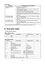
Page 46: ...ting mode 2 The control output remains OFF status OUT1 high limit value is set to 0 or less in Auxiliary function setting mode 2 Set it to a suitable value while in Auxiliary function setting mode 2 If any unexplained malfunctions occur make inquiries at our agency or us 11 Character table Photocopiable material Main setting mode Character Setting item Default value Data SV1 0 SV2 0 Sub setting mo...

Page 47: ...tant 0 0 seconds OUT1 high limit 100 OUT1 low limit 0 OUT1 ON OFF action hysteresis 1 0 OUT2 action mode Air cooling OUT2 high limit 100 OUT2 low limit 0 Overlap band Dead band 0 0 OUT2 ON OFF action hysteresis 1 0 A1 type No alarm action A2 type No alarm action A1 action Energized Deenergized Energized A2 action Energized Deenergized Energized A1 hysteresis 1 0 A2 hysteresis 1 0 A1 action delayed...

Page 48: ... Ushiyama cho Kasugai shi Aichi 486 0901 Japan Phone 81 568 33 7861 FAX 81 568 33 8591 About our sale network please visit our website PRINTED IN JAPAN Panasonic Industrial Devices SUNX Co Ltd 2012 No KT91E7 2013 05 Pursuant to the directive 2004 108 EC article 9 2 Panasonic Electric Works Europe AG Rudolf Diesel Ring 2 83607 Holzkirchen Germany This product has been developed produced for industr...

Reviews: