8
2. Name and functions of the sections
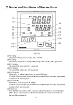
(Fig. 2-1)
(1) PV display
Indicates the PV (process variable) with a red LED.
(2) SV display
Indicates the SV (main set value) or MV (manipulated variable) with a green LED.
(3) SV1 indicator
The green LED lights when SV1 is selected.
(4) SV2 indicator
The yellow LED lights when SV2 is selected.
(5) OUT1 indicator
When OUT1 or Heating output is on, the green LED lights.
(For the DC current output type, this flashes corresponding to the output manipulated
variable in 0.25 second cycles)
(6) OUT2 indicator
When OUT2 is on, the yellow LED lights.
(For the DC current output type, this flashes corresponding to the output manipulated
variable in 0.25 second cycles)
(7) HB indicator
When Heater burnout alarm output or sensor burnout alarm output is on, the red LED lights.
(When Heater burnout alarm is added and if indication is overscale or underscale,
the red LED lights as well)
(1)
(2)
(3)
(4)
(5)
(6)
(7)
(8)
(9)
(10)
(11)
(14)
(15)
(12)
(13)

