19
6 MECHANICAL FUNCTION
6.1.
Paper Feed Mechanism
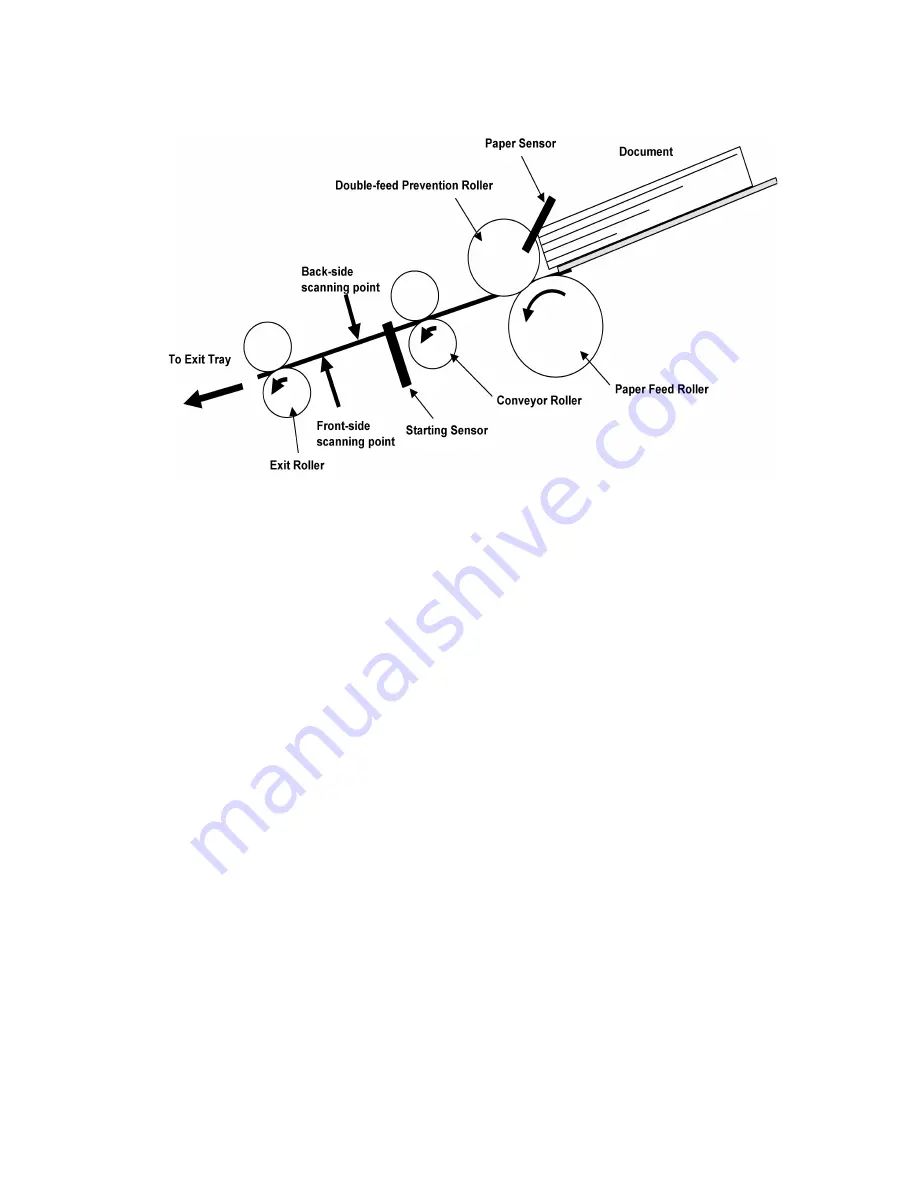
Fig. 6.1
1. When the document is set on the Feed Tray, and its presence is detected by the Paper Sensor, the scanning command
from PC will allow the Conveyor Motor to be driven, which will rotate the Paper Feed Roller, Conveyor Roller, and Exit Roller
in the direction of the arrows.
2. When the document enters into the separation section inside the paper feed section, the Double-feed Prevention Roller
(supported by shaft fixed via a torque limiter) exerts a manipulation force onto the document, which depends on the
set torque.
In case of continuous paper feed, the 1st document is separated from the 2nd or more documents by this manipulation
force, and is fed to the scanning section.
3. When the leading edge of the document advances to the Conveyor Roller position, the document is conveyed at a faster
speed, that is 2.6 times as fast as the speed of the Paper Feed position.
4. When the leading edge of the document pushes down the Starting Sensor’s arm, the leading edge is detected, and
scanning the image will start after a certain interval.
5. When the trailing edge of the document passes through the separation section, the continuous rotation of the Paper Feed
Roller during a series of scanning, enables the following document to be conveyed.
(Different speed between the rotation of the Conveyor Roller and that of the Paper Feed Roller rotation makes up a distance
between the 1st document and the 2nd.)
6. Repeat the above steps 2 to 5.
7. When the Paper Sensor detects no document, and the Starting Sensor detects the trailing edge of the document, the
Conveyor Motor will stop rotating after a certain interval to end a series of scanning sequence.
Note:
When the scanner’s buffer becomes full, the scanner stops to prevent buffer overflow, while allowing the data
to be transferred to the PC continuously. When enough free buffer area is secured again, the scanner resumes
the scanning process
.
Summary of Contents for KV-S1020C SERIES
Page 10: ...10 ...
Page 28: ...28 ...
Page 41: ...41 8 Remove the screw c and the screw d And pull out the Conveyor Motor ...
Page 62: ...62 ...
Page 78: ...78 Fig 10 1 1 Fig 10 1 2 Fig 10 1 3 Fig 10 1 4 Fig 10 1 5 Fig 10 1 6 ...
Page 79: ...79 Fig 10 1 7 Fig 10 1 8 ...
Page 85: ...85 Fig 10 2 5 Fig 10 2 6 Fig 10 2 7 Fig 10 2 8 Fig 10 2 9 ...
Page 86: ...86 ...
Page 89: ...89 11 3 Block Diagram 3 ...
Page 95: ...95 5 2 CONTROL Board KV S1025C Series KV S1020C Series ...
Page 96: ...96 5 3 CONTROL Board KV S1025C Series KV S1020C Series ...
Page 97: ...97 5 4 CONTROL Board KV S1025C Series KV S1020C Series ...
Page 102: ...102 ...
Page 104: ...104 13 1 CONTROL Board 13 1 1 Front Side PbF stamp ...
Page 105: ...105 13 1 2 Back Side ...
Page 109: ...109 14 Parts Location and Mechanical Parts List ...
Page 110: ...110 14 1 Exterior and Chassis ...


