29
8 DISASSEMBLY INSTRUCTIONS
8.1.
Disassembly Flowchart
The flowchart indicates disassembly sequence of the Exterior item, Mechanical parts’ item, Unit Components’ item, and Circuit
Board assemblies’ item. When reassembling, perform the steps in the reverse order unless otherwise instructed in the
Reassembling Notes.
Note:
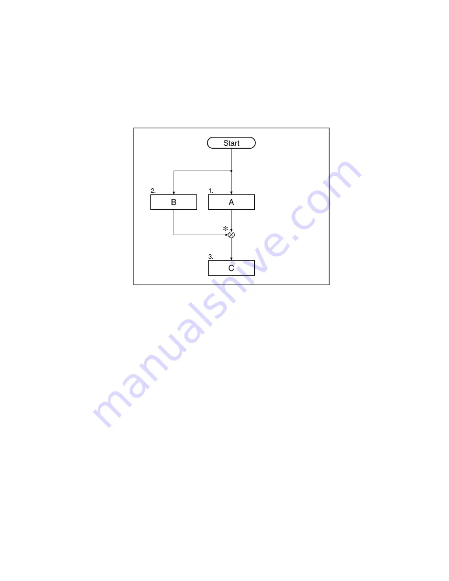
Disassembly flowchart explanation
* This sample flowchart shows that, to disassemble C, procedures 1 and 2 must be performed first before proceeding
to procedure 3.
Summary of Contents for KV-S1025C SERIES
Page 10: ...10 ...
Page 28: ...28 ...
Page 41: ...41 8 Remove the screw c and the screw d And pull out the Conveyor Motor ...
Page 62: ...62 ...
Page 78: ...78 Fig 10 1 1 Fig 10 1 2 Fig 10 1 3 Fig 10 1 4 Fig 10 1 5 Fig 10 1 6 ...
Page 79: ...79 Fig 10 1 7 Fig 10 1 8 ...
Page 85: ...85 Fig 10 2 5 Fig 10 2 6 Fig 10 2 7 Fig 10 2 8 Fig 10 2 9 ...
Page 86: ...86 ...
Page 89: ...89 11 3 Block Diagram 3 ...
Page 95: ...95 5 2 CONTROL Board KV S1025C Series KV S1020C Series ...
Page 96: ...96 5 3 CONTROL Board KV S1025C Series KV S1020C Series ...
Page 97: ...97 5 4 CONTROL Board KV S1025C Series KV S1020C Series ...
Page 102: ...102 ...
Page 104: ...104 13 1 CONTROL Board 13 1 1 Front Side PbF stamp ...
Page 105: ...105 13 1 2 Back Side ...
Page 109: ...109 14 Parts Location and Mechanical Parts List ...
Page 110: ...110 14 1 Exterior and Chassis ...


