72
9.3.8.
Other (Save Information)
Clicking
“Save Info”
on the main menu enables the PC to save the scanner and the PC information as text files.
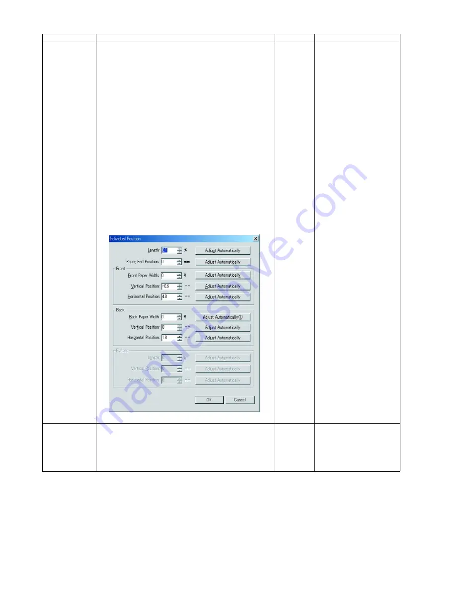
Individual Position 1. Adjust Automatically
a. Set Test Chart A4 (Part No.: See 14.3.) on the Feed Tray
in the
portrait
orientation, according to
"1. Adjust Automatically" in the
Remarks
column.
b. Click
“Individual Position”
on the main menu.
c. Click one of 8 automatic adjustment menu on the
“Individual Position”
dialog box to execute the
adjustment.
d. Check the result.
e. Click
“OK”
to finish this adjustment.
f. Click
“OK”
to get back to the main menu.
2. Adjust Manually
a. Click
“Individual Position”
on the main menu.
b. Change the parameter (mm, %) on the
“Individual
Position”
dialog box, as required. (Refer to Remarks.)
c. Click
“OK”
to apply the new setting, and to get back to the
main menu.
—
1. Adjust Automatically
8 automatic adjustment
(1) Adjust Length.
(2) Adjust Paper-end Position.
(3) Adjust Front Width.
(4) Adjust Front V. Position.
(5) Adjust Front H. Position.
(6) Adjust Back Width.
(7) Adjust Back V. Position.
(8) Adjust Back H. Position.
(1) to (5): Face down the chart
on each individual
adjustment.
(6) to (8) : Face up the chart on
each individual
adjustment
(KV-S1025C Series Only)
2. Adjust Manually
(Length)
+: Increasing a value allows
the scanning image to
extend vertically.
(Paper End Position)
+: On the LC (Length Control)
mode, increasing a value
allows the paper-end timing
to be earlier.
(Width)
-: Decreasing the value
narrows the document width.
(Vertical Position)
+: Increasing the value shifts
the document image position
downward.
(Horizontal Position)
+: Increasing the value shifts
the document image position
to the right.
Note:
If the appropriate
scanning position can not
be obtained by any of the
manual adjustments, check
the Optical Unit
installation.
*USB ID
1. Click
“USB ID”
on the main menu to go into the
USB ID
dialog box.
2. Click
“Set”
on the USB ID dialog box to store a new ID
number for a new replaced CONTROL Board.
3. Click
“Close”
to go back to the main menu.
—
* This setting is available only
for a new replaced
CONTROL Board.
Item
Operation
Default
Remarks
Summary of Contents for KV-S1025C SERIES
Page 10: ...10 ...
Page 28: ...28 ...
Page 41: ...41 8 Remove the screw c and the screw d And pull out the Conveyor Motor ...
Page 62: ...62 ...
Page 78: ...78 Fig 10 1 1 Fig 10 1 2 Fig 10 1 3 Fig 10 1 4 Fig 10 1 5 Fig 10 1 6 ...
Page 79: ...79 Fig 10 1 7 Fig 10 1 8 ...
Page 85: ...85 Fig 10 2 5 Fig 10 2 6 Fig 10 2 7 Fig 10 2 8 Fig 10 2 9 ...
Page 86: ...86 ...
Page 89: ...89 11 3 Block Diagram 3 ...
Page 95: ...95 5 2 CONTROL Board KV S1025C Series KV S1020C Series ...
Page 96: ...96 5 3 CONTROL Board KV S1025C Series KV S1020C Series ...
Page 97: ...97 5 4 CONTROL Board KV S1025C Series KV S1020C Series ...
Page 102: ...102 ...
Page 104: ...104 13 1 CONTROL Board 13 1 1 Front Side PbF stamp ...
Page 105: ...105 13 1 2 Back Side ...
Page 109: ...109 14 Parts Location and Mechanical Parts List ...
Page 110: ...110 14 1 Exterior and Chassis ...


