74
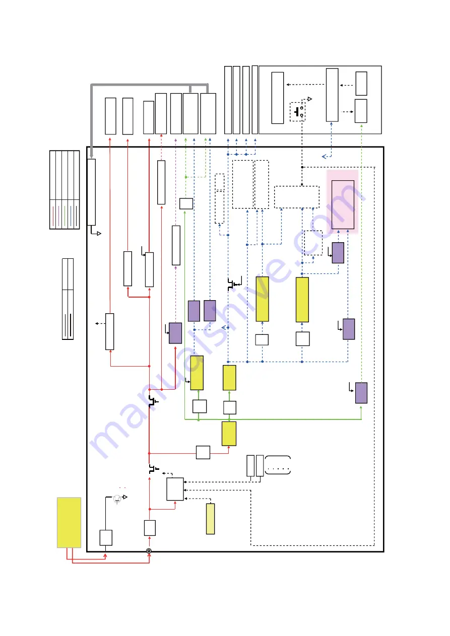
11.3. Block Diagram-3 (Power Supply)
KV-S1057C/KV-SL1066
3.
3V
DC/DC
3.
0A
12V
R
e
g.
150m
A
12V
Fu
s
e
4A
OV
P
Mot
or Driver
1.
8V
SOC
VTT
,
V
re
f
ON/
OFF
Circuit
F2
Q17
30V
,
150m
A
24
V
12V
3.
3V
1.
8V
1.
0V
3.
3V
0.
9V
(voltage
di
v
idi
n
g
)
*S
L
E
E
P
(from A
RM)
24
V
V
DD33
(3
.3
V)
3.
3V
S
L
P
AFE
Q28
So
li
d
l
in
e
M
o
re
th
a
n
1
5
W
D
o
tt
ed l
in
e
L
es
s
t
h
a
n
15W
Conv
ey
or
MM
o
to
r
D
o
u
b
le
F
e
e
d
(G
)
D
o
u
b
le
F
e
e
d
(R
)
F
ro
n
t
C
IS
P
a
n
e
l
POWER_CNT1
Double F
e
ed
(R)
12V_
DFR
B
a
c
k
C
IS
S
ta
rt
S
e
n
s
o
r
P
a
p
e
r
S
e
n
s
o
r
Mot
or Driver
Key
C
O
N
T
R
O
L
B
o
a
rd
(Power But
ton)
CI
S L
E
D
Const
ant
current
circuit
(T
R)
DSC7003S
0L
×6
+6V
+24.5V
7V
DC/DC
3.
0A
Serial
IC
5V
R
e
g
200m
A
3A
,
2
0V
3A
,
40V
15V
,
3
50m
A
,
350m
W
Fu
s
e
0.
5A
USB3
.0
Cont
roller
(KV-S1057C)
+7.
0V
Double F
e
ed Driver
1.
02V
DC/DC
3.
0A
686m
A
81m
A
2A
0.
83A
100mA
+5V_
SLP
3A
,
7
V
BD9B300M
U
V
1.
8V
DC/DC
3.
0A
LC
D
3A
,
7
V
BD9B300M
U
V
Mot
or Driver
Platen M
M
o
to
r
7S
E
G
L
E
D
*S
L
E
E
P
(*
SLEEP)
FPGA
(S
1057C
)
1.
2V
R
e
g
1000m
A
7V
,1
000m
A
,1900
m
W
*S
L
E
E
P
D
o
o
r
S
e
n
s
o
r
A
u
to
/M
a
n
u
a
l
S
e
n
s
o
r
Fus
e
2A
F4
Fu
s
e
2A
F5
3.
3V
3.
3V
Fu
s
e
2A
F3
Fu
s
e
2A
F1
F8
Q36
(*
SLEEP)
+3.
3V
_
C
IS
_
F
+3.3
V
_CI
S
_B
+7.
0V
2.
5V
R
e
g
200m
A
*S
L
E
E
P
206m
A
F9
Fu
s
e
2A
3A
,
20V
*S
L
E
E
P
3.
3V
R
e
g
1000
m
A
3.
3V
R
e
g
1000
m
A
7V
,
1
000m
A
,
1900
m
W
3.
9V
DC/DC
3.
0A
IC
1
4
IC
5
1
IC
5
2
IC
5
3
IC
4
9
IC
4
8
IC
1
7
IC
9
IC
1
2
IC
1
1
IC
1
0
Poly
Swit
ch
CF1
2
4V
_
SLP
Fa
n
c
o
n
trol
c
irc
u
it
F
a
n
M
o
to
r
Fa
n
Error
Fan
E
rror
OFF
ON
Sh
u
tdown
IC
1
8
IC
1
9
OF
F
Condit
ions
Un
de
r S
le
e
p
mode
Powe
r OFF
IC
4
IC
2
6
IC
4
3
SOC (IC4
),
EEPROM
(I
C5
),
Re
s
e
t (I
C6
),
DA
C
(I
C7
),
SPI
F
lash
(I
C8
)
IC
1
8
, 1
9
IC
2
, IC
3
POWER BOARD
24V
12V
7V
Less than 3.3V
Control signal (3.3V)
Summary of Contents for KV-S1027C
Page 7: ...7 ...
Page 9: ...9 3 Location of Controls and Components 3 1 Main Unit ...
Page 10: ...10 ...
Page 16: ...16 5 Section Views 5 1 Motor 5 2 Roller ...
Page 17: ...17 5 3 Board and Sensor ...
Page 31: ...31 7 3 8 Wiring of Upper Chassis ...
Page 128: ...128 14 Exploded View and Replacement Parts List ...
Page 133: ...133 14 3 Feed Tray Assembly 302 305 302 303 307 301 306 305 302 304 Feed Tray Assembly ...
Page 188: ...Index 74 8 Operating Manual Table of Contents ...
Page 255: ...PNQX6995ZA DD0914HS0 Panasonic System Networks Co Ltd 2014 ...


