background image

© Panasonic Corporation 2014 
Unauthorized copying and distribution is a violation
of law.

Order Number KM71411921SE

Category Number G14

Document Scanner

Model No. 

KV-S1057C
KV-S1027C
KV-SL1066
KV-SL1056
KV-SL1055
KV-SL1036
KV-SL1035

Summary of Contents for KV-S1057C
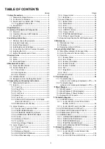
Page 1: ...oration 2014 Unauthorized copying and distribution is a violation of law Order Number KM71411921SE Category Number G14 Document Scanner Model No KV S1057C KV S1027C KV SL1066 KV SL1056 KV SL1055 KV SL...

Page 2: ...Reference Plate B 33 7 4 4 DOOR DETECTION Board 33 7 4 5 Side Plate Assembly 34 7 4 6 Conveyor roller 34 7 4 7 Exit Roller 35 7 5 Lower Chassis 2 36 7 5 1 Bottom Plate 36 7 5 2 Platen Motor 36 7 5 3...

Page 3: ...ssembly 131 14 3 Feed Tray Assembly 133 14 4 Upper Chassis 135 14 5 Lower Chassis 1 137 14 6 Lower Chassis 2 139 14 7 Screw 141 14 8 Packing 142 14 9 Tool 144 14 10 CONTROL Board 145 14 10 1 KV S1027C...

Page 4: ...t on the worktable 4 Do not grasp IC or LSI pins with bare fingers 1 3 About Lead Free Solder PbF Pb free Note In the information below Pb the symbol for lead in the periodic table of elements will re...

Page 5: ...zardous substances RoHS in electrical and electronic equipment effective 1st July 2006 in the EU countries In order for the product to comply with the RoHS Directive the six particular substances lead...

Page 6: ...85 6 x 54 mm 3 4 x 2 1 in Thickness 0 76 mm 0 03 in Feed capacity 3 cards on the feed tray or on the mixed batch card guide 5 sheets Roller replacement 250 000 Tonal Gradation Binary Grayscale Color...

Page 7: ...7...

Page 8: ...1001 KV SL1056 B Brazil G59XXXX1001 KV SL1066 CN China G56XXXX1001 KV SL1056 CN China G61XXXX1001 KV SL1055 CN China G62XXXX1001 KV SL1036 CN China G63XXXX1001 KV SL1035 CN China G64XXXX1001 KV SL1066...

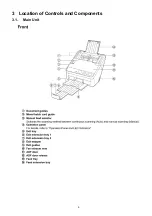
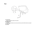
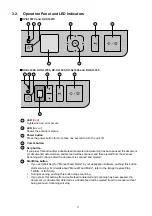
Page 9: ...9 3 Location of Controls and Components 3 1 Main Unit...

Page 10: ...10...

Page 11: ...ocuments detected as a double feed will be scanned and then ejected from the scanner Scanning will continue after the document is scanned and ejected 1 2 3 4 5 Start Stop button If you set Wait Key fo...

Page 12: ...for a certain period of time the scanner will be turned off automatically Press the power button of the scanner to turn it on You can enable disable the power off feature and change the time until the...

Page 13: ...tware Manual CD ROM Trademarks Microsoft Windows Windows Vista Windows Server and Internet Explorer are either registered trademarks or trademarks of Microsoft Corporation in the United States and or...

Page 14: ...the same computer Otherwise the flatbed scanner you would like to use may not operate 3 Be sure to connect the scanner directly to the USB interface port on the PC If you connect the scanner to a USB...

Page 15: ...20 lb 4 When using the Mixed Batch Card Guide the document guides can not be adjusted to a width smaller than A5 5 ISO format card Size 85 6 x 54 0 mm 3 4 x 2 1 in Thickness 0 76 mm 0 03 in Embossed c...

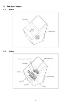
Page 16: ...16 5 Section Views 5 1 Motor 5 2 Roller...

Page 17: ...17 5 3 Board and Sensor...

Page 18: ...r more documents by this force and is fed to the scanning section If a Double Feed occurs when Double Feed detection mode has been set in the scanning software the scanner will stop the scanning proce...

Page 19: ...no further documents and the Starting Sensor detects the trailing edge of the document the Conveyor Motor will stop rotating after a certain period of time determined by the scanner to end the scanni...

Page 20: ...fed to the scanning start position to obstruct the light axis line of the sensor 6 2 3 Door Detector The Door Detector turns OFF when the ADF Door is closed to block the detector with the claw Paper S...

Page 21: ...is the possible state for the Gates to feed docu ments The Document stages start a descent at that time 3 When the Feed drive shaft is rotated 270 in the direction feeding document the Document stage...

Page 22: ...Reference Plate is changed into black background color side Then the Platen Motor slightly rotates clockwise and the Reference Plate is set to black background color 3 When changing the background co...

Page 23: ...l parts Unit Components and Circuit Board assemblies When reassembling perform the steps in the reverse order unless otherwise instructed in Reassembling Notes Note Disassembly flowchart explanation T...

Page 24: ...SL10XX Scanning Glass B AUTO MANUAL DETECTION Board ULTRASONIC SENSOR G BOARD PAPER SENSOR Board Free Roller CIS B 7 3 5 7 3 4 Reference plate F 7 3 6 7 3 3 7 3 2 7 3 7 Double Feed Prevention Roller 7...

Page 25: ...ide of the feed tray arrow 1 first as shown in the illustration 1 Keep pulling the Paper Tray arrow 1 2 Push the 2 levers arrows 2 to unlock the 2 hooks 3 Remove the Feed Tray Cover arrow 3 1 Remove E...

Page 26: ...7 Unlock the 4 hooks of the upper side while expanding the Back Cover 2 arrows 2 8 Remove Back Cover arrow 3 1 Pull the Top Cover 2 arrows 1 at the same time to unlock 2 hooks See PANEL SWITCH Board a...

Page 27: ...d while unlocking the 2 hooks in the direction of the arrows 4 Disconnect the FFC cable 5 Disconnect the PANEL SWITCH Board from the LCD PANEL Board 1 Remove Top Cover See Top Cover P 26 2 Remove the...

Page 28: ...s between the ribs of the pulleys 1 Remove Top Cover See Top Cover P 26 2 Unlock the Hook 3 Remove the PAPER SENSOR Board 4 Disconnect the connector NG Rib Rib Rib Good Double Feed Prevention Roller 1...

Page 29: ...connect the connector 1 Remove Top Cover See Top Cover P 26 2 Unlock the Hook arrow 1 while pushing the boss of the CIS B Assembly arrow 2 3 Remove CIS B Assembly arrow 3 4 Disconnect the FFC cable fr...

Page 30: ...the shafts and the Free Roller Guide Reassembling Note Install 2 pcs of the Free Roller Guide after installing the Free Roller as follows 1 Insert the tab of the Free Roller Guide under the Upper Fra...

Page 31: ...31 7 3 8 Wiring of Upper Chassis...

Page 32: ...rs arrow 2 from the shaft Reassembling Note Make sure the left white and right black paper feed rollers are installed correctly 1 Remove the Back Cover See Back Cover P 26 2 Open the ADF door 3 Remove...

Page 33: ...he Slider groove With the position of the gear maintained install the Slider so that the Slider touches 2 ribs 5 Remove the Polyslider and the Reshuffling Lever 6 Remove the Reference Plate B Rib Slid...

Page 34: ...he Pulley is locked to the Conveyor Roller by pulling the Pulley 3 Slide and remove the bearing from the Conveyor Roller arrow 3 4 Open and remove the Feed Roller Cover 5 Unlock the hook of the Convey...

Page 35: ...3 Slide and remove the Bearing from the Exit Roller arrow 3 4 Unlock the hook of the Conveyor Roller Bearing arrow 4 5 Unlock the Exit Roller by turning the Conveyor Roller Bear ing arrow 5 7 Slide t...

Page 36: ...ottom Plate P 36 2 Remove the screw C 3 Remove the Platen Motor with Motor Plate 4 Remove the 2 screws G and remove the Platen Motor from the plate 1 Remove the Bottom Plate See Bottom Plate P 36 2 Re...

Page 37: ...Remove the screw A 4 Remove the Conveyor Motor with the plate 5 Remove the 2 screws G and remove the Conveyor Motor from the plate 1 Remove the CONTROL Board See CONTROL Board P 36 2 Remove the 3 scre...

Page 38: ...en replac ing Starting Sensor 3 Adjust All Position or the following positions a Adjust Length in Individual Position b Adjust Paper end Position in Individual Position c Adjust Front Vertical Positio...

Page 39: ...or in a place with a temperature over 40 C 104 F Only use the Roller Cleaning Paper to clean the rollers For details about the Roller Cleaning Paper refer to the Material Safety Data Sheet MSDS Pleas...

Page 40: ...s found in this service utility software Note This utility software is not included with the scanner Please call service or technical support to obtain the utility software This software should be use...

Page 41: ...by rotating the Conveyor Motor in the paper feed direction or its reverse direction Feed Used to check paper feed operation 5 LCD test for KV S10xxC 7 segment LED Test for KV SL10xx Used to check LCD...

Page 42: ...nter or Replace Roller Counter is reset 2 Double Feed or Dog ear is detected 1st ON OFF Setting of Roller Cleaning Notification 2nd ON OFF Setting of Roller Replacement Notification Rename the file fr...

Page 43: ...in the document feed tray Double feed error U30 Scanner Door is open Please close the door Door is open or is not closed tightly Or the door detection mechanism does not work properly Fxx System error...

Page 44: ...Other sensor error 7x 8x Hardware error 9x Hardware error ax bx cx dx ex fx Classifi cation Code Error Code Contents ST1 ST2 ST3 ST4 00 00 00 00 No error 0a 00 00 00 Stop by clicking STOP 0b 00 00 00...

Page 45: ...45 F71 9f 00 00 00 Model ID error F80 60 00 00 00 Double Feed Detector Generate or Receive error Classifi cation Code Error Code Contents ST1 ST2 ST3 ST4...

Page 46: ...1 Click Roller Maintenance on the main menu Caution Setting 2 Click Change on Roller Maintenance dialog box to change the parameter value of Clean Roller Timing and Replace Roller Timing 3 Click Rolle...

Page 47: ...d sensor status 4 Click Close to return to the Test menu Conveyor Motor 1 Click Test on the main menu 2 Click Conveyor Motor on the Test menu 3 Click START to start the Conveyor Motor rotation 4 Click...

Page 48: ...an white paper A4 80 g m2 or Letter 20lb between the Scanning Glass F and Scanning Glass B Then close the ADF Door 4 Set the value for Gain Value 40 or less 5 Select a side Front or Back and resolutio...

Page 49: ...e ADF Door and then remove the white paper Then close the ADF Door 9 Click Close to return to the Test menu Memory 1 Click Test on the main menu 2 Click Memory on the Test menu 3 Click START to start...

Page 50: ...nt side Face down 2nd page Back side Face up Individual Position 1 Click Adjust on the main menu 2 Adjust Automatically a Set Test Chart A4 Part No See Tool P 144 on the Feed Tray in portrait orientat...

Page 51: ...K on the Double Feed Detector dialog box to return to the Adjust menu 3 Adjust Manually a Click Double Feed on the Adjust menu b Change the parameter Send Level c Click OK to return to the Adjust menu...

Page 52: ...Power Button to turn on the scanner 2 Release the Buttons START STOP Button and Power Button when the LEDs change to match the status in the right column LED Red OFF LED Green ON OFF ON 3 Set documen...

Page 53: ...ns START STOP Button and Power Button when the LEDs change to match the status in the right column LED Red ON LED Green ON ON ON 3 Push the START STOP Button once to turn on the CIS F See Note below O...

Page 54: ...heir surrounding circuits on the CONTROL Board Q15 Q16 Q17 4 Monitor the following signals 1 Q15 C E Typ 0 V 2 Q16 C E Typ 0 V 5 Replace faulty parts 7 CONTROL Board does not work properly 1 Perform t...

Page 55: ...and of their surrounding circuits on the CONTROL Board and then repair it 1 JK1 USB IF connector 2 FL1 Common mode filter 3 IC4 CPU 2 Replace the CONTROL Board START STOP Button Skip Button or Cursor...

Page 56: ...the scanning position can be adjusted properly 2 The CIS assembly is not installed properly 1 Re assemble the CIS Assembly See Disassembly and Assembly Instructions P 23 The document skews when scanne...

Page 57: ...R28 3 Monitor the following CIS Timing signals on the CN1 1 CLK See Fig 10 1 1 2 SI See Fig 10 1 2 4 Replace faulty parts or boards 4 Problem with Pixel data from CIS B or from the image processing ci...

Page 58: ...Rollers under the Conveyor Motor test 3 Replace the Bearing that have the the strange sound 3 Problem with the Rollers 1 Perform the Conveyor Motor test in Sec Test P 47 2 Check the rotating sound fro...

Page 59: ...59 Fig 10 1 1 Fig 10 1 2 CN1 5 Pixel Clock KV S1027C KV SL1056 55 36 35 CN1 5 Pixel Clock KV S1057C KV SL1066 CN1 7 Start line KV S1027C KV SL1056 55 36 35 CN1 7 Start line KV S1057C KV SL1066...

Page 60: ...il it clicks into place 5 Paper dust exists on or around the Starting Sensor 1 Clean up the dirt with cleaning paper or cotton swab or soft and dry cloth See Sec Disassembly Flowchart P 23 2 Execute K...

Page 61: ...ions of this scanner 10 CIS B is not installed properly 1 Re attach the CIS B See Upper Chassis P 28 2 Perform the Feed test in Sec Test P 47 U12 Conveyor Jam Paper jammed around the Starting Sensor 1...

Page 62: ...r does not work correctly 1 Execute Key Sensor test in Sec Test P 47 to check the sensor condition 2 Check the sensor alignment is proper whether the sensor direction faces to its light guide 3 Check...

Page 63: ...s Paper Feed Double Feed Prevention are dirty 1 Clean the Rollers 2 After cleaning the Paper Feed Roller and Double Feed Prevention Roller perform the Clear Counter After Clean Roller in the service u...

Page 64: ...83 b CN13 2nd pin See Fig 10 2 4 7 Replace faulty parts or boards 6 Double Feed Detector Receive does not work properly 1 Perform Double Feed test in Sec Test P 47 to check the detector condition 2 Pe...

Page 65: ...PU IC4 3 R163 R168 R171 R172 R1175 2 Replace faulty parts or board F60 Front side gain adjustment error 50 00 00 00 1 The surface of Scanning Glass F is dirty Clean the surface with a soft and dry clo...

Page 66: ...ns and soldering condition on each connector a CIS B Unit to CN2 CONTROL Board 5 Check the power supply for LED 1 CN2 7th pin F8 7 0 V 2 L4 L5 L8 Q10 Q11 Q12 6 Replace faulty parts or boards 3 Problem...

Page 67: ...V S1027C KV SL1056 1055 1036 1035 Check whether black dots are stamped on the CONTROL Board s silk The black dots indicate the supported Model No If no replace the board F80 Double Feed Detector error...

Page 68: ...68 Fig 10 2 1 Fig 10 2 2 CN1 5 Pixel Clock KV S1027C KV SL1056 55 36 35 CN1 5 Pixel Clock KV S1057C KV SL1066 CN1 7 Start line KV S1027C KV SL1056 55 36 35 CN1 7 Start line KV S1057C KV SL1066...

Page 69: ...69 Fig 10 2 3 Fig 10 2 4 Fig 10 2 5 CN8 1 Motor OUT Note Frequency depends on each model CN13 2 US OUT S1057C CN9 1 R415 US AMP_OUT...

Page 70: ...Sensor DOOR Auto Manual Sensor Auto Manual 128MByte 1Gbit 16bit bus DDR2 DDR2 IC20 IC20 Panel KEY Power Start Stop Skip Up Down LED Ready Error USB3 0 Connector Clock Genelator OVL106 ACH11 ACH09 ACH1...

Page 71: ...K VSMP RSMP OP 7 0 AFE IC3 SEN SCK SDI OEB VRLC VREF VREF EEPROM IC5 WP SCL SDA 4Kbit XIN1 XOUT1 RESETN RINP GINP BINP MCLK VSMP RSMP OP 7 0 AFE IC2 SEN SCK SDI OEB VRLC USB Device USB2 0 Connector GP...

Page 72: ...olor image data 6 After handling the above process the CPU IC4 stores the data into the DDR2 Memory IC20 IC21 7 Controlled by USB Controller in the CPU IC4 the processed data is transmitted from DDR2...

Page 73: ...D CN2001 CN 13 CN012 Contact image sensor Contact image sensor To PC POWER SUPPLY JK02 CN06 CN 02 AUTO MANUAL AUTO MANUAL DETECT ION BOARD CN2401 DOOR DETECT ION BOARD CN2101 CN010 PAPER SENSOR BOARD...

Page 74: ...Controller KV S1057C 7 0V Double Feed Driver 1 02V DC DC 3 0A 686mA 81mA 2A 0 83A 100mA 5V_SLP 3A 7V BD9B300MUV 1 8V DC DC 3 0A LCD 3A 7V BD9B300MUV Motor Driver Platen M M otor 7SEG LED SLEEP SLEEP...

Page 75: ...CIS LED Constant current circuit TR DSC7003S0L 6 6V 24 5V 7V DC DC 3 0A Serial IC 5V Reg 200mA 3A 20V 3A 40V 15V 350mA 350mW Fuse 0 5A USB3 0 Controller KV S1027C 7 0V Double Feed Driver 1 02V DC DC...

Page 76: ...DE Resolution control 9 14 FVREF CIS Reference Voltage 10 13 3 3V Power Supply for CIS 11 12 GND Ground 12 11 FCIS5 Pixel data 5 13 10 GND Ground 14 9 FCIS4 Pixel data 4 15 8 GND Ground 16 7 FCIS3 Pix...

Page 77: ...RD CN03 CN4000 CN5000 1 1 POWER_SW Power SW Detect 2 2 KRESET RESET Signal 3 3 KSCLK Serial Clock 4 4 KRXD Serial RXD 5 5 KSTXD Serial TXD 6 6 KSSTART START Signal 7 7 GND Ground 8 8 3 3V 3 3V 9 9 5V...

Page 78: ...3 3V Power Supply 2 2 AUTO AUTO Detect Signal 3 3 GND Ground CN13 CONTROL BOARD CN2001 USS G BOARD CN13 CN2001 1 1 GND Ground 2 2 U_SONIC_G2 Generate signal 2 for Ultra Sonic Sensor 3 3 U_SONIC_G1 Ge...

Page 79: ...CD PANEL Board KV S10xxC 12 3 PANEL SWITCH Board KV S10xxC 12 4 PANEL Board KV SL10xx 12 5 SENSOR Board 12 5 1 ULTRASONIC SENSOR G Board 12 5 2 DOOR DETECTION Board 12 5 3 PAPER SENSOR Board 12 5 4 ST...

Page 80: ...16 OP3 14 OP1 15 OP2 L10 CL28 CL27 CL21 R27 47 R18 1 5k AGND AGND C51 1000p AGND C54 1000p AGND R25 47 R21 1 5k AGND C55 1000p AGND R26 47 R22 1 5k R28 47 R19 1 5k AGND AGND C52 1000p R77 1k C68 100p...

Page 81: ...VL07 AB4 OVL06 AB5 OVL05 AA1 OVL04 AA2 OVL03 AA3 OVL02 AA4 OVL01 AA5 OVL00 LED_FOUT_B 1 2B LED_FOUT_G 1 2B LED_FOUT_R 1 2B LED_BOUT_R 1 2F LED_BOUT_G 1 2F LED_BOUT_B 1 2E CIS_CLK 1 1D R97 47 R98 47 R9...

Page 82: ...37 7p R229 1 C136 22p GND CL215 R216 1M START_LED_DAC 8 5D START_COMP_DAC 8 7E R217 47 R218 47 R187 100 R188 100 CL196 CL199 CL200 R205 47k 1 2 3 4 5 6 7 8 R186 47k 1 2 3 4 5 6 7 8 R198 47k R199 47k R...

Page 83: ...N1 2 PVIN2 3 PGND1 4 PGND2 5 AGND 6 FB 7 FREQ 8 MODE 9 SS 10 SW1 11 SW2 12 SW3 17 FIN 16 AVIN 15 EN 14 PGD 13 BOOT C157 K0 1u GND C154 K0 1u GND C153 1000p PGD 4 6E R272 47k C151 0 1u 50 R274 47k R273...

Page 84: ...5 VIN 1 VOUT 3 CE 2 VSS D24 3 3V_SLP CL291 GND C204 10u 10 C203 0 1u 3 3V_CIS_F 7 0V C209 0 1u CL287 R308 0 R310 0 R312 0 R311 0 GND C215 10u 10 C212 0 1u 3 3V_CIS_B 7 0V C221 0 1u CL299 3 3V_SLP 3 3...

Page 85: ...15 GND R317 22k GND R318 22k R335 R334 0 GND IC18 1 VM1 2 NC1 30 IN3 31 ENABLEA 3 BOUT2 32 TJMON 4 NC2 29 IN2 5 RCSB 28 IN1 6 NC3 27 IN0 7 BOUT1 26 PHB1 8 NC4 25 PHA1 9 AOUT2 24 PWMSW 10 NC5 23 GND 11...

Page 86: ...4B GND R372 10k DDR_CLK0 7 3C 7 4B DDR_CLK1 7 3C 7 7B R374 10k R375 10k DDR_NCLK1 7 3C 7 7B 1 8V_DDR2 DDR_VREF_ 0 9V C263 10u 6 3 C262 K0 1u 10 C276 K0 1u C278 K0 1u C274 K0 1u 1 8V_DDR2 C275 K0 1u C...

Page 87: ...00 GND C305 1000p AUTO MANUAL 12 6D GND C296 1000p C299 K0 1u GND 3 3V_SLP C289 1000p C293 K0 1u GND GND C284 1000p GND C285 1000p GND CL348 GND C286 1000p C287 K0 1u GND GND C288 1000p C291 K0 1u GND...

Page 88: ...R476 2 7k R480 270 R474 2 2k R481 3 9k C343 0 01u GND GND R475 47k C346 0 1u C336 0 1u R483 47k R479 270 Q31 3 2 1 6 5 4 C340 0 1u GND GND C345 0 1u CL407 C348 0 1u GND R485 47k R482 3 9k R477 47k Q3...

Page 89: ...R493 4 7k 1 GND R492 3k 1 R488 47k R487 47k GND GND R489 47k R490 47k GND GND R491 3k 1 R494 47k GND 3 3V CL479 R1092 47k GND R1093 47k GND IC4 AF10 PCIECLKM0 AE10 PCIECLKP0 AF17 PCIECLKM1 AE17 PCIEC...

Page 90: ...30 4 7k R528 4 7k GND 3 3V_UDVCC 3 3V_UDVCC R520 4 7k USB3_SSTXM 11 6E USB3_SSTXP 11 6E USB3_SSRXP 11 6E USB3_SSRXM 11 6E USB3_DM 11 6D USB3_DP 11 6E C418 2 2u 10 GND R549 1K R510 47 R511 47 R529 47 G...

Page 91: ...DR8 T22 VDDDDR9 U22 VDDDDR10 V22 VDDDDR11 W22 VDDDDR12 Y22 VDDDDR13 C16 DVDDT33 C15 H0VDDT33 C14 H1VDDT33 T9 LVDSTVDD33 P9 LVDSRVDD10 V12 PCIEVDDA0 V15 PCIEVDDA1 AD8 PCIEVDDHA0_1 AD9 PCIEVDDHA0_2 AD11...

Page 92: ...201 VSSO23 202 VDDO21 203 SAH02 204 SAH03 205 SAH04 206 SAH05 207 TSIGH 208 NC17 1 NC1 2 NC2 3 VDDREF 4 SAH06 5 SAH07 6 SAH08 7 SAH09 8 VSSO1 9 VDDO1 10 SAH10 11 SAH11 12 SAH12 13 SAH13 14 VDDO2 15 V...

Page 93: ...I O12 11 VCC1 34 VSS2 12 VSS1 33 VCC2 13 I O4 32 I O11 14 I O5 31 I O10 15 I O6 30 I O9 16 I O7 29 I O8 17 WE 28 NC2 18 A16 27 A8 19 A15 26 A9 20 A14 25 A10 21 A13 24 A11 22 A12 23 NC1 R1039 22 GND 3...

Page 94: ...C37 100p R21 1 5k 3 3V_SLP R661 47 AGND AGND AGND R662 47 C55 1000p BD 9 0 15 1C C33 K0 1u 10 AGND C441 K0 1u GND AGND R26 47 GND C13 K0 1u 10 R22 1 5k C442 K0 1u C462 100p AGND R28 47 C443 K0 1u C45...

Page 95: ...DSCKN 15 6B FLVDSCKP 15 6C FLVDSD0P 15 6B FLVDSD0N 15 6B FLVDSD1P 15 6B FLVDSD1N 15 6B FLVDSD2P 15 6B FLVDSD2N 15 6B R214 100 R283 100 R353 100 R354 100 BLVDSD0P 15 6C BLVDSCKP 15 6C BLVDSD0N 15 6C BL...

Page 96: ...47 R218 47 R187 100 R188 100 CL196 CL199 CL200 R205 47k 1 2 3 4 5 6 7 8 R186 47k 1 2 3 4 5 6 7 8 R198 47k R207 47k R206 47k R210 47k GND GND D38 1 2 3 POWER_SW_SOC 12 5C 5V_SLP 3 3V 3 3V 3 3V 3 3V 3 3...

Page 97: ...6 FB 7 FREQ 8 MODE 9 SS 10 SW1 11 SW2 12 SW3 17 FIN 16 AVIN 15 EN 14 PGD 13 BOOT C157 K0 1u GND C154 K0 1u GND C153 1000p PGD 4 6E R272 47k C151 0 1u 50 R274 47k R273 1k GND C161 100p GND GND R277 0...

Page 98: ...IN 3 ON OFF 1 VOUT 2 VSS1 4 NC 5 VSS2 GND R1251 47k SLEEP 1 8C 5 1C 5 2B 5 3D 5 4C 5 6B 6 6E 12 8B C616 0 1u R1252 1k 3 3V 2 5V_SLP D43 C624 0 1u CL758 GND C622 10u 6 3 C621 0 1u C623 10u 6 3 IC49 4 N...

Page 99: ...D R317 22k GND R318 22k R335 R334 0 GND IC18 1 VM1 2 NC1 30 IN3 31 ENABLEA 3 BOUT2 32 TJMON 4 NC2 29 IN2 5 RCSB 28 IN1 6 NC3 27 IN0 7 BOUT1 26 PHB1 8 NC4 25 PHA1 9 AOUT2 24 PWMSW 10 NC5 23 GND 11 RCSA...

Page 100: ...0k DDR_CLK0 7 3C 7 4B DDR_CLK1 7 3C 7 7B R374 10k R375 10k DDR_NCLK1 7 3C 7 7B 1 8V_DDR2 DDR_VREF_ 0 9V C263 10u 6 3 C262 K0 1u 10 C276 K0 1u 10 C278 K0 1u 10 C274 K0 1u 10 1 8V_DDR2 C275 K0 1u C266 K...

Page 101: ...5 1000p AUTO MANUAL 12 6D GND C296 1000p C299 K0 1u GND 3 3V_SLP C289 1000p C293 K0 1u GND GND C284 1000p GND C285 1000p GND CL348 GND C286 1000p C287 K0 1u GND GND C288 1000p C291 K0 1u GND 3 3V_SLP...

Page 102: ...M R476 2 7k R480 270 R474 2 2k R481 3 9k C343 0 01u GND GND R475 47k C346 0 1u C336 0 1u R483 47k R479 270 Q31 3 2 1 6 5 4 C340 0 1u GND GND C345 0 1u CL407 C348 0 1u GND R485 47k R482 3 9k R477 47k Q...

Page 103: ...R493 4 7k 1 GND R492 3k 1 R488 47k R487 47k GND GND R489 47k R490 47k GND GND R491 3k 1 R494 47k GND 3 3V CL479 R1092 47k GND R1093 47k GND IC4 AF10 PCIECLKM0 AE10 PCIECLKP0 AF17 PCIECLKM1 AE17 PCIEC...

Page 104: ...3 4 7k R530 4 7k R528 4 7k GND 3 3V_UDVCC 3 3V_UDVCC R520 4 7k USB3_SSTXM 11 6E USB3_SSTXP 11 6E USB3_SSRXP 11 6E USB3_SSRXM 11 6E USB3_DM 11 6D USB3_DP 11 6E C418 2 2u 10 GND R549 1K R510 47 R511 47...

Page 105: ...11 W22 VDDDDR12 Y22 VDDDDR13 C16 DVDDT33 C15 H0VDDT33 C14 H1VDDT33 T9 LVDSTVDD33 P9 LVDSRVDD10 V12 PCIEVDDA0 V15 PCIEVDDA1 AD8 PCIEVDDHA0_1 AD9 PCIEVDDHA0_2 AD11 PCIEVDDHA0_3 AD12 PCIEVDDHA0_4 AD13 PC...

Page 106: ...205 SAH04 206 SAH05 207 TSIGH 208 NC17 1 NC1 2 NC2 3 VDDREF 4 SAH06 5 SAH07 6 SAH08 7 SAH09 8 VSSO1 9 VDDO1 10 SAH10 11 SAH11 12 SAH12 13 SAH13 14 VDDO2 15 VSSO2 16 SAH14 17 SAH15 18 SAH16 19 SAH17 20...

Page 107: ...1 33 VCC2 13 I O4 32 I O11 14 I O5 31 I O10 15 I O6 30 I O9 16 I O7 29 I O8 17 WE 28 NC2 18 A16 27 A8 19 A15 26 A9 20 A14 25 A10 21 A13 24 A11 22 A12 23 NC1 R1039 22 GND 3 3V_SLP R1070 22 PM36SRAMCS 1...

Page 108: ...FLVDSD0P 2 3C FLVDSD0N 2 3C SPAFEB 1 6D FLVDSCKP 2 3B R587 22 FLVDSCKN 2 3B R129 22 R589 22 SPI_WD 3 5B 3 6B 3 6C 15 3C R332 22 SD0CLK 3 5C R460 100 C197 1u GND C213 K0 1u R459 10k GND GND GND C158 10...

Page 109: ...3 N10 GND24 P5 GND25 P12 GND26 R2 GND27 R15 GND28 E2 GND29 H16 GND30 H15 GND31 M5 GNDA1 E12 GNDA2 3 3V_SLP GND CONF_DONE 12 5B IC47 1 B 2 A 3 GND 4 Y 5 VCC R320 10k R322 1k R203 22 R127 22 R329 0 R319...

Page 110: ...MDLNAME0 1 2D IC4000 34 LATCH 1 KSL2 2 LED6 12 KIN5 23 RS A0 IP 3 KIN1 4 LED7 KSL4 5 XLED8 6 XLED9 7 KIN2 8 KIN3 9 XLED10 10 KSL3 11 KIN4 13 KIN6 14 KIN7 15 XLED12 16 XLED11 17 VDD1 18 VSS1 19 XLED13...

Page 111: ...2 SW4103 1 2 R4106 180 KSL0 1 4D SW4101 1 2 KEYIN_UP 1 4D SW4105 1 2 R4105 180 KEYIN_SET 1 4E KEYIN_SKIP 1 4D SW4104 1 2 R4103 180 KEYIN_RIGHT 1 4D CN4100 1 2 3 4 5 6 7 8 9 10 KEYIN_UP 1 3A KEYIN_SKI...

Page 112: ...004 560p C5007 150p C5008 1000p C5010 390p C5013 100p C5009 10u CL5025 R5024 100 C5005 560p R5025 100 R5026 100 C5011 100p C5006 560p GND 3 3V C5012 0 1u C5014 100p CL5017 GND CL5018 SW5004 SKQNAED010...

Page 113: ...ONIC SENSOR G Board 6 A D C B 5 4 2 3 D A B C CN2001 GND 1 U_SONIC_G2 2 U_SONIC_G1 3 GND 4 SN2001 CL2001 CL2002 GND CN2002 1 From Control Board Ultrasonic Sensor G ULTRASONIC SENSOR G Board KV S1057C...

Page 114: ...Board 6 A D C B 5 4 2 3 D A B C IC2101 2 1 4 3 R2102 0 CL2103 R2101 0 CL2101 CL2102 R2103 0 C2101 0 1u CN2101 1 2 3 R2104 100 DOOR DETECTION SENSOR DOOR SENSOR Board DOOR 3 3V_SLP GND KV S1057C KV S1...

Page 115: ...1027C PAPER SENSOR Board 6 A D C B 5 4 2 3 D A B C IC2201 2 1 4 3 CL2202 CL2203 CL2201 R2202 0 R2203 0 R2201 0 CN2202 RT 01T 1 3B LF 1 C2201 0 1u CN2203 RT 01T 1 3B LF 1 CN2201 1 2 3 R2204 100 PAPER S...

Page 116: ...L2302 R2302 0 R2301 0 CL2303 CL2301 GND Q2302 E C GND R2304 2 7k GND Q2301 R2303 2 2k C2301 0 1u CN2301 1 US AMP_OUT 2 12V 3 GND 4 GND 5 3 3V_SLP 6 START_LED 7 START_PHOTO_TR 8 GND US AMP_OUT 5 6D 12V...

Page 117: ...3 100 R2305 680 R2315 1k R2308 100 C2303 1u 16 C2304 1u 16 C2305 1u 16 C2306 0 01u C2302 1u 16 GND GND GND GND GND GND GND 12V 12V CL2305 R2310 47k C2309 0 1u SN2301 CL2304 C2307 10u 25 C2308 10u 25 U...

Page 118: ...d KV S1057C KV S1027C AUTO MANUAL 7 7 21 Board 6 A D C B 5 4 2 3 D A B C IC2401 2 1 4 3 CL2402 R2402 0 R2401 0 CL2403 CL2401 R2403 0 C2401 0 1u CN2401 1 2 3 R2404 100 AUTO MANUAL 7 7 21 Board AUTO MAN...

Page 119: ...2 LCD PANEL Board KV S10xxC 13 3 PANEL SWITCH Board KV S10xxC 13 4 PANEL Board KV SL10xx 13 5 SENSOR Board 13 5 1 ULTRASONIC SENSOR G Board 13 5 2 DOOR DETECTION Board 13 5 3 PAPER SENSOR Board 13 5 4...

Page 120: ...528 L18 R1218 R335 R141 R529 R1219 L19 R336 C108 R144 R915 R147 R917 R148 R530 L20 C300 R919 L21 R531 R532 L22 R533 L23 R534 C110 R535 L25 C305 IC1 L26 R536 R537 IC4 C114 R920 C309 L29 R151 R921 R539...

Page 121: ...106 R143 C107 R338 R145 R339 R1029 R146 R1220 R725 R1221 R149 R1222 R726 R727 C303 R1223 R340 R1224 R728 R1030 C111 R729 R1031 R341 R1225 C306 R1226 IC2 C112 R343 C307 IC3 C113 R1227 R150 C308 R344 R1...

Page 122: ...47 R530 R148 C300 L20 R919 R531 L21 L22 R532 L23 R533 R534 C110 C305 R535 L25 L26 R342 R536 R537 C114 R538 R920 IC4 L29 C309 R151 R921 R539 R922 IC7 R923 C118 R924 IC9 C119 R925 R1039 C501 C502 R732 R...

Page 123: ...0 R119 R204 R696 C536 R374 C307 C138 C525 R733 C494 R1087 R319 R1092 C155 Q35 R1228 C600 R974 C221 C603 X4 Q37 R22 R492 C115 C538 R13 R453 R231 C462 C488 R266 R1166 C421 R1023 C573 R303 R1204 C250 R61...

Page 124: ...R4010 R4019 R4020 R4021 R4022 R4023 R4024 R4025 R4026 R4027 R4028 R4029 R4030 R4031 CL4000 CL4001 CL4002 CL4003 CL4004 CL4005 CL4006 CL4007 CL4008 CL4009 CL4010 CL4011 CL4012 CL4013 CL4014 CL4015 CL4...

Page 125: ...2 CL5003 CL5004 CL5005 CL5006 CL5007 CL5008 CL5009 CL5010 CL5011 CL5012 CL5013 CL5014 CL5015 CL5016 CL5017 CL5018 CL5019 CL5020 CL5021 CL5022 CL5023 CL5024 CL5025 CL5026 CL5027 C5000 C5001 C5002 C5003...

Page 126: ...ack Side CL2001 CL2002 3 4 1 2 USG Board 2 3 1 4 A PNLPS1057CSZ DOOR DETECTION Board Front Side DOOR DETECTION Board Back Side C2101 R2101 R2102 R2103 R2104 CL2101 CL2102 CL2103 1 3 A Door Detection B...

Page 127: ...2304 C2305 Q2301 C2306 C2307 C2308 C2309 R2301 R2302 R2303 R2304 R2305 R2306 R2307 R2308 R2309 IC2301 R2310 R2311 R2312 R2313 R2314 R2315 R2316 E 1 8 E C 1 8 A PNLPS1057CSZ Starting Sensor Board USR B...

Page 128: ...128 14 Exploded View and Replacement Parts List...

Page 129: ...129 14 1 Exterior Top Cover Assembly Feed Tray Assembly Upper Chassis Lower Chassis 110 111 111 112 113 104 102 105 106 107 108 109 101 103 C H 105 105 105...

Page 130: ...t Cover PS 105 PFHA1001Z Foot Rubber 106 PNKS1053Z1 Exit Tray 1 PS 107 PNKS1054Z1 Exit Tray 2 PS 108 PNKS1055Z1 Exit Tray 3 PS 109 PNKS1056Z1 Exit Tray Stopper PS 110 PNKS1052Z1 Feed Extension Tray fo...

Page 131: ...131 14 2 Top Cover Assembly 202 C 201 C 207 204 203 C 205 206 Top Cover Assembly When replacing the parts should be bent to conform to the current products Only for KV SL10xx...

Page 132: ...r KV SL1066 U 202 PNGK1052X Panel Sheet for KV SL1056 except KV SL1056 U 202 PNGK1059Y Panel Sheet for KV SL1056 U 202 PNGK1053X Panel Sheet for KV SL1036 CN 202 PNGK1054X Panel Sheet for KV SL1035 CN...

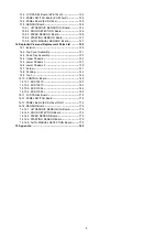
Page 133: ...133 14 3 Feed Tray Assembly 302 305 302 303 307 301 306 305 302 304 Feed Tray Assembly...

Page 134: ...Assist Roller for KV SL10xx POM 303 PNKR1048Z1 Document Guide L for KV S1057C KV S1027C PS 303 PNKR1048Z2 Document Guide L for KV SL10xx PS 304 PNKR1049Z1 Document Guide R for KV S1057C KV S1027C PS...

Page 135: ...432 435 435 403 434 426 429 427 425 425 428 428 433 431 430 434 406 446 445 407 406 407 406 406 424 411 421 412 416 417 418 424 447 448 449 449 448 423 413 422 420 414 419 418 410 B B B 436 437 440 45...

Page 136: ...SL10xx PS 423 PNUR1040Z Hook Spring 424 PNUF1056Z Upper Hook POM 425 PNUG1039Z Free Roller Guide POM 426 PNUF1067Z DFP Roller Holder POM 427 PNUR1046Z DFP Spring 428 PNDR1048Z DFP Roller 429 PNZRS157...

Page 137: ...536 534 535 530 546 531 520 C C A A A C 526 523 546 529 528 409 From Upper Chassis 543 542 527 541 540 545 522 536 536 544 524 521 532 524 510 509 512 507 506 E D C 505 515 516 548 517 501 514 503 50...

Page 138: ...S1057C KV SL1066 523 N2GBYY000002 CIS F for KV S1027C KV SL10xx except KV SL1066 524 PNUR1013Z CIS Spring 525 PNJE1214Z CIS F FFC for KV S1057C KV SL1066 525 PNJE1212Z CIS F FFC for KV S1027C KV SL10x...

Page 139: ...609 602 605 A 623 617 630 630 630 608 C C C C F C C C C F A C C 604 606 601 613 612 626 628 624 618 615 614 616 620 C 611 629 607 625 617 622 621 617 627 620 603 605 G 610 E G C C C Lower Chassis 2 On...

Page 140: ...ith cable for KV S1057C SL1066 623 L6HBYYYB0008 Conveyer Motor with cable for KV S1027C KV SL10xx except KV SL1066 624 PNME1056Z Motor Bracket 625 PNWPS1570M CONTROL Board for KV S1057C RTL PbF 625 PN...

Page 141: ...141 14 7 Screw Illustration Part No A B C D E G H F XTW3 6LFJ XTW3 W10PFJ XYN3 J6FJ XTS3 6FFJ XYN4 F6FJ XTW3 8PFJ8 XTW26 8PFJ7 XTW3 U10PFJ...

Page 142: ...142 14 8 Packing P1 50 mm 2 in Attach the Ferrite Core P12 to the USB Cable P9 as indicated above P4 P12 P3 P11 P2 P5 P6 P9 P8 P7 P10...

Page 143: ...7 PNJA1094Z AC Cord for KV S1057C U KV S1027C U KV SL1066 U KV SL1056 U UK P8 K2CG3YY00063 AC Cord for KV S1057C M J KV S1027C M J KV SL1066 M KV SL1056 M P8 PNJA1114Z AC Cord for KV S1057C U KV S1027...

Page 144: ...144 14 9 Tool Safety Ref No Part No Part Name Description Remarks T1 PNQE1093Z J Shading sheet 10 PIECES T2 PBQX90095Z J Test chart A 10 PIECES T3 RMA02M705 08 Eco solder T1 T2 T3...

Page 145: ...00013 TRANSISTOR SI Q37 DRC9144E0L TRANSISTOR SI Q38 DRC9124E0L TRANSISTOR SI Q39 DRC9144E0L TRANSISTOR SI Q40 DRC9124E0L TRANSISTOR SI Q41 B1ADGE000012 TRANSISTOR SI Q42 DRC9124E0L TRANSISTOR SI Q43...

Page 146: ...09 ERJ2GEJ473 47k R210 ERJ2GEJ473 47k Safety Ref No Part No Part Name Description Remarks R211 ERJ2GEJ473 47k R212 ERJ2GEJ473 47k R213 ERJ2GEJ473 47k R214 ERJ2GEJ473 47k R215 ERJ2GEJ105X 1M R216 ERJ2G...

Page 147: ...22 R446 ERJ2GEJ472X 4 7k R447 ERJ2GEJ473 47k Safety Ref No Part No Part Name Description Remarks R448 ERJ2GEJ473 47k R449 ERJ2GEJ473 47k R450 ERJ2GEJ473 47k R451 ERJ3GEYJ470 47 R452 ERJ3GEYJ473 47k R...

Page 148: ...2 7k R1160 ERJ3GEYJ562 5 6k Safety Ref No Part No Part Name Description Remarks R1161 ERJ3GEY0R00 0 R1162 ERJ3GEYJ392 3 9k R1163 ERJ2GEJ101 100 R1165 ERJ3GEY0R00 0 R1166 ERJ6GEY0R00 0 R1168 ERJ3GEY0R...

Page 149: ...CQ 7p S Safety Ref No Part No Part Name Description Remarks C136 ECUE1H220JCQ 22p C137 ECUE1H7R0DCQ 7 C138 ECUE1A104KBQ 0 1 C139 ECUE1A104KBQ 0 1 C140 ECUE1A104KBQ 0 1 C141 ECUE1A104KBQ 0 1 C145 ECUE1...

Page 150: ...ECUE1A104KBQ 0 1 C352 ECUE1A104KBQ 0 1 C353 ECUE1A104KBQ 0 1 C354 ECUE1A104KBQ 0 1 Safety Ref No Part No Part Name Description Remarks C355 ECUE1A104KBQ 0 1 C360 ECUE1A104KBQ 0 1 C361 ECJ0EB0J105K 1 C...

Page 151: ...G1V1010021 100 C617 F1J0J2260004 22 Safety Ref No Part No Part Name Description Remarks C619 ECUE1A104KBQ 0 1 C621 ECUE1A104KBQ 0 1 C622 ECUE1A104KBQ 0 1 C623 ECUE1A104KBQ 0 1 C625 ECUE1A104KBQ 0 1 C6...

Page 152: ...RAY R979 D1H84734A042 RESISTORS ARRAY R1097 D1H84734A042 RESISTORS ARRAY CRYSTAL OSCILLATORS X2 H0J120500078 CRYSTAL OSCILLATOR X3 H0J120500078 CRYSTAL OSCILLATOR X4 H0J250500097 CRYSTAL OSCILLATOR X5...

Page 153: ...4R10XJ101 100 S R95 PQ4R10XJ101 100 S R96 ERJ2GEJ220 22 R97 ERJ2GEJ220 22 R98 ERJ2GEJ220 22 R99 ERJ2GEJ220 22 R100 ERJ2GEJ220 22 Safety Ref No Part No Part Name Description Remarks R101 ERJ2GEJ473 47k...

Page 154: ...k R286 ERJ3RBD332 3 3k R287 ERJ3RBD123 12k Safety Ref No Part No Part Name Description Remarks R288 ERJ3GEYJ102 1k R290 ERJ3GEYJ102 1k R292 ERJ3EKF3302 33k R294 ERJ3GEYJ102 1k R296 ERJ3GEYJ104 100k R2...

Page 155: ...47k R490 ERJ2GEJ473 47k R491 ERJ2RKF302X 3k R492 ERJ2RKF302X 3k R493 ERJ3EKF4701 4 7k Safety Ref No Part No Part Name Description Remarks R494 ERJ2GEJ473 47k R495 ERJ3EKF6041 6 04k R499 ERJ3GEY0R00 0...

Page 156: ...Safety Ref No Part No Part Name Description Remarks R925 ERJ2GEJ473 47k R927 ERJ2GEJ473 47k R928 ERJ2GEJ473 47k R929 ERJ2GEJ473 47k R930 ERJ2GEJ473 47k R931 ERJ2GEJ473 47k R932 ERJ2GEJ473 47k R933 ER...

Page 157: ...1299 ERJ3GEYJ103 10k Safety Ref No Part No Part Name Description Remarks R1300 ERJ2GEJ220 22 R1301 ERJ2GEJ220 22 R1302 ERJ2GEJ220 22 R1303 ERJ2GEJ220 22 R1304 ERJ3GEYJ103 10k R1305 ERJ3GEY0R00 0 R1306...

Page 158: ...1 C258 ECUE1A104KBQ 0 1 C259 ECUE1A104KBQ 0 1 Safety Ref No Part No Part Name Description Remarks C260 ECUE1C103KBQ 0 01 C261 F1H0J1060003 10 C264 ECUE1A104KBQ 0 1 C265 ECUE1A104KBQ 0 1 C266 ECUE1A104...

Page 159: ...UE0J105KBQ 1 C432 ECUE1C103KBQ 0 01 C434 ECUE0J105KBQ 1 Safety Ref No Part No Part Name Description Remarks C435 ECUE1A104KBQ 0 1 C436 ECUE0J105KBQ 1 C438 ECUE0J105KBQ 1 C439 ECUE1A104KBQ 0 1 C441 ECU...

Page 160: ...F1H0J1060003 10 C634 F1H0J1060003 10 C635 F1H0J1060003 10 Safety Ref No Part No Part Name Description Remarks C636 F1H0J1060003 10 C637 ECUV1H221JCV 220p C641 F1K1E1060001 10 C642 F2G1V1010021 100 C6...

Page 161: ...042 RESISTORS ARRAY R658 D1H84704A042 RESISTORS ARRAY R941 D1H84734A042 RESISTORS ARRAY R942 D1H84734A042 RESISTORS ARRAY R943 D1H84734A042 RESISTORS ARRAY R944 D1H84734A042 RESISTORS ARRAY R955 D1H84...

Page 162: ...NSISTOR SI Q39 DRC9144E0L TRANSISTOR SI Q40 DRC9124E0L TRANSISTOR SI Q41 B1ADGE000012 TRANSISTOR SI Q42 DRC9124E0L TRANSISTOR SI Q43 B1ABCF000011 TRANSISTOR SI DIODES D1 DA2J10100L DIODE SI D2 DA2J101...

Page 163: ...R215 ERJ2GEJ105X 1M R216 ERJ2GEJ105X 1M Safety Ref No Part No Part Name Description Remarks R217 ERJ2GEJ470 47 R218 ERJ2GEJ470 47 R219 ERJ2GEJ470 47 R220 ERJ2GEJ470 47 R221 ERJ2GEJ470 47 R222 ERJ2GEJ...

Page 164: ...3GEYJ470 47 R452 ERJ3GEYJ473 47k R453 ERJ2GEJ473 47k Safety Ref No Part No Part Name Description Remarks R454 ERJ6GEYJ221 220 R458 ERJ6GEYJ221 220 R464 ERJ3GEY0R00 0 R465 ERJ3GEYJ101 100 R466 ERJ3GEYJ...

Page 165: ...2GEJ473 47k R1182 ERJ2GEJ473 47k Safety Ref No Part No Part Name Description Remarks R1183 ERJ2GEJ473 47k R1184 ERJ2GEJ473 47k R1185 ERJ2GEJ473 47k R1186 ERJ2GEJ473 47k R1187 ERJ2GEJ473 47k R1189 ERJ2...

Page 166: ...V 100p Safety Ref No Part No Part Name Description Remarks C162 F1J0J2260004 22 C165 ECUE1A104KBQ 0 1 C166 F1L1V106A003 10 C167 ECUE1H102KBQ 0 001 C168 F1J1A2260003 22 C169 ECUV1C104KBV 0 1 S C170 F1J...

Page 167: ...C502 ECUE1A104KBQ 0 1 C503 ECUE1A104KBQ 0 1 C515 ECUE1A104KBQ 0 1 Safety Ref No Part No Part Name Description Remarks C523 ECUE1A104KBQ 0 1 C525 ECUE1A104KBQ 0 1 C527 ECUE1A104KBQ 0 1 C532 F1H0J106000...

Page 168: ...000216 IC FILTER L39 J0JYC0000220 IC FILTER L40 J0JYC0000220 IC FILTER FUSE F1 K5H202Y00003 FUSE F2 K5G402Y00002 FUSE F3 K5H202Y00003 FUSE F4 K5H202Y00003 FUSE F5 K5H202Y00003 FUSE F7 K5H202Y00003 FUS...

Page 169: ...TOR SI Q32 DRC9124E0L TRANSISTOR SI Q33 B1ABCF000011 TRANSISTOR SI Q34 B1ABCF000011 TRANSISTOR SI Q35 B1ABCF000011 TRANSISTOR SI Q36 B1CHRE000013 TRANSISTOR SI Q37 DRC9144E0L TRANSISTOR SI Q38 DRC9124...

Page 170: ...J473 47k R211 ERJ2GEJ220 22 R212 ERJ2GE0R00 0 Safety Ref No Part No Part Name Description Remarks R213 ERJ2GE0R00 0 R214 ERJ2GEJ101 100 R215 ERJ2GEJ105X 1M R216 ERJ2GEJ105X 1M R217 ERJ2GEJ470 47 R218...

Page 171: ...R387 ERJ2GEJ220 22 Safety Ref No Part No Part Name Description Remarks R388 ERJ2GEJ220 22 R389 ERJ2GEJ220 22 R390 ERJ2GEJ220 22 R391 ERJ2GEJ220 22 R392 ERJ2GEJ220 22 R396 ERJ2GEJ101 100 R413 ERJ2GEJ47...

Page 172: ...R617 ERJ2GEJ220 22 R618 ERJ2GEJ220 22 Safety Ref No Part No Part Name Description Remarks R621 ERJ2GEJ220 22 R623 ERJ2GEJ220 22 R625 ERJ2GEJ220 22 R626 ERJ2GEJ220 22 R628 ERJ2GEJ220 22 R629 ERJ2GEJ47...

Page 173: ...GEJ390 39 R1221 ERJ2GEJ390 39 R1222 ERJ2GEJ390 39 R1223 ERJ2GEJ390 39 Safety Ref No Part No Part Name Description Remarks R1224 ERJ2GEJ390 39 R1225 ERJ2GEJ390 39 R1226 ERJ2GEJ390 39 R1227 ERJ2GEJ390 3...

Page 174: ...F1H0J1060003 10 C190 F1J1A106A024 10 Safety Ref No Part No Part Name Description Remarks C191 F1H0J1060003 10 C192 F1J1A106A024 10 C194 F1H0J1060003 10 C196 F1H0J1060003 10 C198 ECUV1H101JCV 100p C199...

Page 175: ...ECUE1A104KBQ 0 1 C421 ECUE1A104KBQ 0 1 C422 ECUE1A104KBQ 0 1 C423 ECUE1A104KBQ 0 1 Safety Ref No Part No Part Name Description Remarks C424 ECUE1A104KBQ 0 1 C425 ECUE1A104KBQ 0 1 C426 ECUE1A104KBQ 0...

Page 176: ...V1H221JCV 220p C627 F1J1A106A024 10 C628 F1J1A106A024 10 Safety Ref No Part No Part Name Description Remarks C629 ECUV1C104KBV 0 1 S C631 ECUV1C104KBV 0 1 S C632 ECUV1C104KBV 0 1 S C633 F1H0J1060003 1...

Page 177: ...tion Remarks R657 D1H84704A042 RESISTORS ARRAY R658 D1H84704A042 RESISTORS ARRAY R941 D1H84734A042 RESISTORS ARRAY R942 D1H84734A042 RESISTORS ARRAY R943 D1H84734A042 RESISTORS ARRAY R944 D1H84734A042...

Page 178: ...0H1BA000259 SPECIAL SWITCH SW4102 K0H1BA000259 SPECIAL SWITCH SW4103 K0H1BA000259 SPECIAL SWITCH SW4104 K0H1BA000259 SPECIAL SWITCH SW4105 K0H1BA000259 SPECIAL SWITCH SW4106 K0H1BA000259 SPECIAL SWITC...

Page 179: ...SISTOR SI Q2302 B3HA00000065 TRANSISTOR SI DIODE D2301 B3EA00000219 DIODE SI RESISTORS R2307 ERJ3GEYJ101 100 R2308 ERJ3GEYJ101 100 R2313 ERJ3GEYJ101 100 R2316 ERJ3GEYJ101 100 R2309 ERJ3GEYJ102 1k R231...

Page 180: ...180 15 Appendix The extract from an Operating Manual N K KVS1057C KVS1027C KVSL1066 KVSL1056 KVSL1055 KVSL1036 KVSL1035...

Page 181: ...ner These instructions contain information on operating the scanner Before reading these instructions please read the Quick Installation Guide enclosed with this unit Keep all documentation in a safe...

Page 182: ...detection function Yes Yes Yes Yes Yes Yes Yes Double Feed Skip DFS function Yes Yes Yes Yes Yes Yes Yes Card scanning Yes Yes Yes Yes Yes Yes Yes Mixed batch card guide Yes Yes Yes Yes Yes Yes Yes M...

Page 183: ...nner has a push scan function for starting scanning without operation through a computer Scanning is started by selecting from settings that have been registered in advance with the cursor button and...

Page 184: ...ft Windows Windows Vista and Internet Explorer are either registered trademarks or trademarks of Microsoft Corporation in the United States and or other countries ISIS is a registered trademark or tra...

Page 185: ...rmation and outlines brief installation procedures of the unit and software About the Software Help Each software contains help files For details about viewing the help files see To view the help page...

Page 186: ...used Due to the slower speed of USB 1 1 it is recommended to use a USB 2 0 USB 3 0 interface If you connect the unit to a USB hub it is not guaranteed to work Optional Accessories Part Name Part Numb...

Page 187: ...mages 31 Continuous Scanning Auto and Manual Scanning Manual 32 Mixed Batch Card Guide 33 Installing the mixed batch card guide 33 Removing the mixed batch card guide 35 Using the Mixed Batch Card Gui...

Page 188: ...Index 74 8 Operating Manual Table of Contents...

Page 189: ...e Installation Do not place the unit in direct sunlight in a cold draft or near heating apparatus Do not place the unit near apparatus which generate electronic or magnetic noise Protect the unit from...

Page 190: ...the roller cleaning paper KV SS03 please contact your dealer or call our Supplies and Accessories department at 1 800 726 2797 U S A only KEEP AWAY FROM FIRE Security Notice The management of document...

Page 191: ...ROM Drivers Applications Utilities Documents Mixed batch card guide When the unit is shipped this is stored in the feed tray Quick Installation Guide Power cord Two power cords may be included Use the...

Page 192: ...ous scanning Auto and manual scanning Manual Operation panel For details refer to Operation Panel and LED Indicators page 14 Exit tray Exit extension tray 1 Exit extension tray 2 Exit stopper Exit gui...

Page 193: ...slot Use a commercially available security cable USB connector USB cable Connect the USB cable to the scanner and the other end of the USB cable to the computer Power cord AC inlet Operating Manual 1...

Page 194: ...status C Power button Press the power button for more than one second to turn the unit off D Cursor button E Skip button If you press this button after a double feed is detected and scanning has been...

Page 195: ...Scanning will stop n KV S1057C and KV S1027C only G LCD H OK button If you are using the scanner with Image Capture Plus you can perform a push scan using the LCD Registered jobs are displayed on the...

Page 196: ...of time the scanner will be turned off automatically Press the power button of the scanner to turn it on You can enable disable the power off feature and change the time until the scanner turns off i...

Page 197: ...surrounding objects as shown in the following illustration 272 mm 10 7 in 300 mm 11 8 in 500 mm 20 in 750 mm 30 in 238 mm 9 4 in 400 mm 16 in Notice Do not move the unit immediately from a cold place...

Page 198: ...s applications utilities and Operating Manual b Custom Install one of the software or Operating Manual Note Normally it is recommended to select Complete 1 Check that the unit has been turned off If t...

Page 199: ...ct the item that you want to install Note If you select TWAIN or ISIS Image Capture Plus will also be installed 6 Follow the instructions on the screen and complete the installation Restart your compu...

Page 200: ...t 1 Remove all packing tape and cushioning 2 Pull out the feed extension tray in the direction of the arrow shown in the illustration below 3 Set the exit tray a Raise the exit stopper 20 Operating Ma...

Page 201: ...tray or the exit extension trays Doing so may damage them 4 Plug in the power cord and connect the USB cable 5 Press the power button to turn ON the unit s power The LED Green will flash and then turn...

Page 202: ...indows 8 select the Panasonic Document Scanner section on the Apps screen To view the help Note We recommend that you view the help using Internet Explorer 6 0 or later for Windows For Image Capture P...

Page 203: ...matches the number of pages in the feed tray Also check the condition of the scanned documents Remove documents from the exit tray after they have been scanned Compatible Paper Types Paper size Width...

Page 204: ...L 14 in 8 mm 0 31 in 80 64 g m 17 lb High quality woodfree paper 80 75 g m 20 lb High quality woodfree paper 80 80 g m 21 lb High quality woodfree paper Recommended paper types High quality woodfree...

Page 205: ...andscape orientation with the side to be scanned facing up A maximum of 3 cards can be loaded on the feed tray When loading ensure that the embossed portions of cards do not stick together Use the lan...

Page 206: ...use an optional carrier sheet KV SS076 to scan passports using manual scanning Passport size The passport sizes compatible with this unit are as follows Width 140 mm 5 5 in or less Length 190 mm 7 5...

Page 207: ...carrier sheet B first as shown in the illustration The corner of the thinner part of the passport should be inserted into the corner of the carrier sheet 1 2 3 Place the carrier sheet A on the feed tr...

Page 208: ...ned image will be stretched or distorted In such cases clean the rollers If vertical streaks appear on the scanned image clean the scanning glasses and the carrier sheet Vertical streaks that appear m...

Page 209: ...photographs that are susceptible to damage such as scratching Scanning the following kinds of documents may contaminate the inside of the scanner or adversely influence the lifetime of the rollers Wh...

Page 210: ...gs set Feeding Speed to Slow 1 Scan the documents using manual scanning 1 For details about configuring the scan settings refer to the Image Capture Plus TWAIN or ISIS help Notes about Double Feed Det...

Page 211: ...round Color of Scanned Images Using the software you can switch the background color of scanned images between white and black For details refer to the Image Capture Plus TWAIN or ISIS help Operating...

Page 212: ...canned by setting the manual feed selector to manual scanning Manual Continuous scanning Auto This setting is for feeding documents one page at a time automatically Manual scanning Manual This setting...

Page 213: ...ard simultaneously Installing the mixed batch card guide The mixed batch card guide is stored inside the feed tray Install the mixed batch card guide as shown in the following illustration 1 Remove th...

Page 214: ...3 Attach the feed tray A to the unit 1 4 Attach the mixed batch card guide A to the unit 1 34 Operating Manual Operation...

Page 215: ...tch card guide as shown in the following illustration 1 Remove the mixed batch card guide A from the unit 1 2 Remove the feed tray A from the unit Remove the left side of the feed tray B first as show...

Page 216: ...3 Attach the mixed batch card guide B to the feed tray A 1 2 4 Attach the feed tray A to the unit 1 36 Operating Manual Operation...

Page 217: ...the card in landscape orientation A maximum of 3 cards can be set in the mixed batch card guide Ensure that the embossed portions of cards do not stick together If acceptable results cannot be obtain...

Page 218: ...Scanning Documents 1 Adjust the document guides A slightly larger than the actual size of the documents 1 38 Operating Manual Operation...

Page 219: ...l the edges Hold both ends and bend the documents as shown in the illustration To flatten the documents hold firmly and pull them apart as shown in the illustration 1 2 3 Repeat these steps as necessa...

Page 220: ...in the illustration A Insert the documents slowly until they stop 1 Note The height of the documents should not exceed the limit mark on the document guide Exceeding the limit mark may cause a paper...

Page 221: ...curs fold up the exit guides C and then resume scanning 3 7 Open your scanning application and scan the documents For details about the application refer to the help of each application You can also s...

Page 222: ...n 2 Select Touch Free Scanning for the condition to automatically start up the application 3 Select the application to start up Note For details about the Scan Button Setting Tool refer to the Scan Bu...

Page 223: ...Register jobs in advance For details about registering jobs refer to the Image Capture Plus help The group name is displayed on the first line and the job name is displayed on the second line of the L...

Page 224: ...registered job number is displayed on the 7 segment LED Use the cursor button A to select a job number Note Register jobs in advance For details about registering jobs refer to the Image Capture Plus...

Page 225: ...Panel Scanners and Cameras select the scanner icon and then click the Properties button If you are using Windows XP Control Panel Scanners and Cameras right click the scanner icon and display the Pro...

Page 226: ...trol sheets from the included CD ROM B S i m p l e x A Documents Control sheet Code Documents Control sheet functions Simplex Duplex Binary 256 level gray Color Dynamic Threshold Dither Error diffusio...

Page 227: ...n the Image Capture Plus TWAIN or ISIS help Printing control sheets Note In order to print control sheets Adobe Reader must be installed on your computer Refer to the instruction manual for your print...

Page 228: ...sheet according to the following procedure 1 Remove all documents from the feed tray 2 Press the ADF door release A and open the ADF door B 2 1 3 Remove the jammed document If the document is jammed...

Page 229: ...forward as shown in the illustration 4 Close the ADF door Push both sides of the ADF door down slowly until it clicks into place Notice Close the ADF door after confirming that no documents remain ins...

Page 230: ...e cleaners detergent thinner or benzine Doing so may cause deformation discoloration or damage Clean the scanner at least once a month 1 Clean the outside of the scanner with a soft slightly damp clot...

Page 231: ...Be careful not to damage any parts of the unit 1 Prepare the following cleaning supplies Soft and dry cloth Used to clean the conveyor and scanning glasses Thin cotton swab Used to clean the double f...

Page 232: ...he Conveyor and Scanning Glasses page 53 Cleaning the Double Feed Detectors and Starting Sensors page 54 Cleaning the Rollers page 55 4 Close the ADF door After cleaning push both sides of the ADF doo...

Page 233: ...Cleaning the Conveyor and Scanning Glasses 1 With a soft and dry cloth wipe off any dirt on the conveyor A and scanning glasses B 1 2 Operating Manual 53 Care and Maintenance...

Page 234: ...Cleaning the Double Feed Detectors and Starting Sensors 1 Remove dust from the double feed detectors A and starting sensors B with a cotton swab 2 1 1 2 54 Operating Manual Care and Maintenance...

Page 235: ...Open the double feed prevention roller cover A 1 2 Remove the double feed prevention roller While pushing the latch A to the right side as the direction indicated by the arrow remove the double feed p...

Page 236: ...surface of both rollers 4 Install the double feed prevention roller Align the shaft that is shaped as indicated by A with the notch in the roller mount B and then insert the shaft in the notch Push t...

Page 237: ...ble feed prevention roller cover A firmly 1 Notice Be sure to close the double feed prevention roller cover until it clicks into place 6 Open the paper feed roller cover A 1 Operating Manual 57 Care a...

Page 238: ...rom one end to the other in the direction of the arrow all the way around them as shown in the illustration 8 Close the paper feed roller cover firmly Make sure to close both sides of the paper feed r...

Page 239: ...on on the scanner is pressed 1 2 Note Do not touch the rollers while they are rotating Use Cleaning Mode only for cleaning the conveyor rollers and exit rollers 10 Use the roller cleaning paper to cle...

Page 240: ...sheets is based on scanning high quality woodfree paper Depending on the type of paper and other factors the actual lifetime for the rollers will differ In User Utility you can check the number of she...

Page 241: ...when facing it from the notch in the roller mount 2 1 4 Take out the new double feed prevention roller module in the optional roller exchange kit 5 Install the double feed prevention roller Align the...

Page 242: ...ble feed prevention roller cover A firmly 1 Notice Be sure to close the double feed prevention roller cover until it clicks into place 7 Open the paper feed roller cover A 1 62 Operating Manual Care a...

Page 243: ...en remove the paper feed roller 1 9 Remove the rubber rollers from the paper feed roller shaft Push the tab A to remove the rubber roller B from the paper feed roller shaft Remove the other rubber rol...

Page 244: ...ert the rubber rollers onto the paper feed roller shaft until they click into place 1 1 Notice Inserting a rubber roller with the tab facing inwards may damage the roller 12 Install the paper feed rol...

Page 245: ...the feeding direction 14 Close the ADF door Push both sides of the ADF door down slowly until it clicks into place 15 Reset the After Replace Roller Counter in User Utility to 0 For details refer to...

Page 246: ...he software from the computer page 70 and then install the software again page 18 The scanner is connected via USB hub Do not connect via USB hub There is a problem with the USB cable Make sure to use...

Page 247: ...g method is set to manual Select automatic scanning using the manual feed selector page 12 A double feed is detected when scanning cards The cards are set in portrait orientation Either disable the do...

Page 248: ...ter than it appears Setting the value for Chroma higher in the scanning conditions may solve this problem Dark spots or noise appear on the scanned documents The scanning glasses are dirty Clean the s...

Page 249: ...a Open the ADF door and remove the paper The sensors are dirty Clean the sensors U16 The paper has jammed in the exit tray area Open the ADF door and remove the paper The sensors are dirty Clean the s...

Page 250: ...IDR Engine Panasonic System Networks Co Ltd Panasonic Scanner Manuals Panasonic System Networks Co Ltd Panasonic Document Scanner Device Driver Panasonic System Networks Co Ltd MCD Panasonic System Ne...

Page 251: ...e charge to repair the scanner Please use the original carton and all of the original packing materials The scanner should be handled in the correct horizontal position Required Materials Original sca...

Page 252: ...y should be less than 10 mm 0 4 in 130 sheets 64 g m 17 lb High quality woodfree paper 100 sheets 75 g m 20 lb High quality woodfree paper 100 sheets 80 g m 21 lb High quality woodfree paper Card 4 Fo...

Page 253: ...models Scanning 40 W or less 35 W or less 35 W or less 35 W or less 35 W or less Ready 8 W or less 8 W or less 8 W or less 8 W or less 8 W or less Sleep 3 0 W or less For KV S1057C and KV S1027C 2 9...

Page 254: ...st vent 12 Feed extension tray 12 Feed tray 12 I Incompatible Documents 29 L LCD 2 15 43 LED Green 14 16 LED Red 14 16 M Manual feed selector 2 3 12 32 Mixed batch card guide 2 3 11 12 33 O OK button...

Page 255: ...PNQX6995ZA DD0914HS0 Panasonic System Networks Co Ltd 2014...

Reviews: