background image

©

2002 Kyushu Matsushita Electric Co., Ltd.

All rights reserved. Unauthorized copying and

distribution is a violation of law.

KV-S2025C Series
KV-SU225C Series
KV-S2045C Series
KV-SU245C Series

High Speed Color Scanner

ORDER NO. KM70206776C0

G14

Summary of Contents for KV-S2025C

Page 1: ...shita Electric Co Ltd All rights reserved Unauthorized copying and distribution is a violation of law KV S2025C Series KV SU225C Series KV S2045C Series KV SU245C Series High Speed Color Scanner ORDER NO KM70206776C0 G14 ...

Page 2: ...unction item list of Service Utility 61 9 3 Operation 62 9 4 Scanner Self test 68 10 TROUBLESHOOTING 69 10 1 Troubleshooting 1 with no error message on PC 69 10 2 Troubleshooting 2 according to Error Code or Scanner Status in Service Utility 69 10 3 Requirement After Parts Replacement 79 11 CIRCUIT DESCRIPTION 80 11 1 Block Diagram 1 Image Processing 80 11 2 Block Diagram 2 Board 82 11 3 Explanati...

Page 3: ...he unit unplugged short the AC Live Neutral of the plug with a jumper wire 3 Turn ON the power switch 4 Measure the resistance value with an ohmmeter between the jumpered AC plug and each exposed metal cabinet part such as screwheads etc Note Some exposed parts may be isolated from the chassis by design They read infinity 5 If the measurement is less than 1M a possibility for electric shock may ex...

Page 4: ...e careful not to heat too long PbF solder will tend to splash if it is heated much higher than its melting point approximately 1100 F 600 C If you must use Pb solder on a PCB manufactured using PbF solder remove as much of the original PbF solder as possible and be sure that any remaining is melted prior to applying the Pb solder When applying PbF solder to double layered boards please check the c...

Page 5: ...2 10 7 to 33 9 lbs Continuous paper feeding 50 to 127g m2 13 3 to 33 9 lbs Note 1 lbs 3 75 g m2 Interface Transfer rate SCSI 20 MB sec Feed tray capacity 120 sheets 64 g m2 17 lbs 100 sheets 75 g m2 20 lbs Unit External dimensions Width Depth Height 343 487 269 mm 13 5 19 2 10 6 in Note When tray is pulled 343 487 239 mm 13 5 19 2 9 4 in Note When tray is installed Weight 8 4 kg 18 5 lbs 9 1kg 20 ...

Page 6: ...upply AC100 to AC120V is applied U Europe and other countries where power supply AC220 to AC240V is applied except for China CN For China 3 The setting of the paper length is possible to 25 inches in TWAIN ISIS and RTIV In case of a paper beyond legal size 1 by 1 paper scanning in the resolution under 300dpi is recommended 2 2 KV SU225C SU245C Series Item Model No KV SU225C Series KV SU245C Series...

Page 7: ...tch Power Cord This illustration is a sample figure for AC100 120V AC Inlet Connectors Color ON Green Orange Red 1 Ready 2 Scanning 1 Ready with warning error 2 Scanning with warning error An error occurred Flashing Sleeping without warning error 1 Initializing 2 Sleeping with warning error 3 Shading System error LED for indicating scanner status Note Warning error Clean roller or replace roller 7...

Page 8: ...ension Tray Only for KV S2045C SU245C Series Take out the Feed Extension Tray and Exit Extension Tray in the accessory carton box and install them as shown below Note Don t carry the scanner with the Feed Extension Tray and the Exit Extension Tray Be sure to remove the trays before carrying the scanner 8 KV S2025C Series KV SU225C Series KV S2045C Series KV SU245C Series ...

Page 9: ...4 4 System Requirements 4 4 1 KV S2025C S2045C Series CPU Minimum Pentium 300MHz Recommended Pentium 800MHz or higher Memory RAM Black White Scanning Minimum 128MB Recommended 256MB or higher Color Scanning Minimum 256MB Recommended 512MB or higher OS Windows 95 Windows 98 Windows Me Windows NT Windows 2000 Windows XP SCSI Board Adaptec SCSI card 2930U 2940U 29160N 19160 Note The scanning speed di...

Page 10: ...FF ON 2 OFF ON OFF 3 OFF ON ON 4 ON OFF OFF 5 ON OFF ON 6 ON ON OFF KME Factory Default 7 ON ON ON Note It is not until restarting the PC after restarting the scanner that Setting SCSI ID will be activated 4 5 2 Terminator According to the SCSI interface condition set the Terminator TERM ON or OFF Note 1 If the scanner is the last or the only device in the SCSI chain the terminator should be set t...

Page 11: ...Contact Image Sensor Sensor Roller Back Sensor Roller Front CIS Back CIS Front Imprinter Option KV S2045C SU245C Series only Conveyor Motor Paper Feed Motor 11 KV S2025C Series KV SU225C Series KV S2045C Series KV SU245C Series ...

Page 12: ...5 2 Rollers Exit Roller Drive Rollers Retard Roller Separation Roller Paper Feed Roller 12 KV S2025C Series KV SU225C Series KV S2045C Series KV SU245C Series ...

Page 13: ...5 3 Circuit Boards LED Board RELAY BACK Board RELAY FRONT Board CONTROL Board POWER Board POWER SW Board Power Switch 13 KV S2025C Series KV SU225C Series KV S2045C Series KV SU245C Series ...

Page 14: ...tch ENDING SENSOR Board Ending Sensor STARTING POSITION SENSOR Board Starting Position Sensor Door Switch WAITING SENSOR Board Waiting Sensor Paper Detector 14 KV S2025C Series KV SU225C Series KV S2045C Series KV SU245C Series ...

Page 15: ...the separation section and Waiting Sensor the Paper Feed Motor stops and the Paper Feed Roller and Separation Roller turn together 5 When the leading edge of the document passes through Starting Position Sensor scanning the image starts after the defined period Time to be required to conveyor the documents from the Starting Position Sensor to the scanning start point 6 When the heeling edge of the...

Page 16: ...anner starts scanning again 6 2 2 In case the data size of a document is within the amount of the memory in the scanner 1 Same sequence as the above sequence 1 of the 6 1 says 2 Same sequence as the above sequence 2 of the 6 1 says 3 Same sequence as the above sequence 3 of the 6 1 says 4 Same sequence as the above sequence 4 of the 6 1 says 5 Same sequence as the above sequence 5 of the 6 1 says ...

Page 17: ...n Sensor Ref No 63 in Sec 14 2 C C C C C Reflector Sheet for Ending Sensor Ref No 35 in Sec 14 1 C C C C C Note The above values for each maintenance item are registered in the maintenance counter Refer to Sec 9 and the PC will inform users the cleaning or replacing timing if the utility software in this scanner has been already installed The maintenance schedule was determined according to paper ...

Page 18: ...ller Cleaning Paper or Model KV SS03 Option Roller Cleaning Paper Note When wiping off the dirt on the roller surfaces hold the rollers to prevent from rotating and wipe the rollers all the way around them proceeding from one end to the other in the direction of the arrows shown in the figure 4 Remove the Retard Roller Cover in the direction of the arrow shown in the figure 18 KV S2025C Series KV ...

Page 19: ...all the way around it proceeding from one end to the other in the direction of the arrow shown in the figure 6 And then assemble the Retard Roller Cover 7 Close the ADF Door slowly until it clicks into place Note After cleaning the above rollers execute Clear Counter for cleaning roller in Service Utility See 9 3 4 19 KV S2025C Series KV SU225C Series KV S2045C Series KV SU245C Series ...

Page 20: ...sory Roller Cleaning Paper or Model KV SS03 Option Roller Cleaning Paper 4 Clean the surfaces of the Free Rollers with the accessory Roller Cleaning Paper or Model KV SS03 Option Roller Cleaning Paper When cleaning them wipe off the dirt on the roller surfaces all the way around them proceeding from one end to the other in the direction of the arrows shown in the figure 20 KV S2025C Series KV SU22...

Page 21: ...Door slowly until it clicks into place 7 2 3 Cleaning CIS and Sensor Rollers 1 Turn off the scanner 2 Push the ADF Door Release to open the ADF Door 21 KV S2025C Series KV SU225C Series KV S2045C Series KV SU245C Series ...

Page 22: ...l KV SS03 Option Roller Cleaning Paper 4 Wipe off the glass surface on the CIS Front and the Sensor Roller Back in the direction of the arrows shown in the figure with the accessory Roller Cleaning Paper or Model KV SS03 Option Roller Cleaning Paper 5 Close the ADF Door slowly until it clicks into place 22 KV S2025C Series KV SU225C Series KV S2045C Series KV SU245C Series ...

Page 23: ... Door 3 Sweep out the dirt from the Paper Detector Waiting Sensor and Starting Position Sensor with a soft cotton swab 4 Sweep out the dirt from the Reflector Sheets for the Waiting Sensor and Starting Position Sensor with a soft cotton swab 23 KV S2025C Series KV SU225C Series KV S2045C Series KV SU245C Series ...

Page 24: ...rrows with the accessory Roller Cleaning Paper or Model KV SS03 Option Roller Cleaning Paper 3 Clean the surfaces of the Free Rollers in the direction of the arrows with the accessory Roller Cleaning Paper or Model KV SS03 Option Roller Cleaning Paper 4 Sweep out the dirt from the Ending Sensor and its Reflector Sheet with a soft cotton swab 24 KV S2025C Series KV SU225C Series KV S2045C Series KV...

Page 25: ... open the ADF Door 3 Push down the two Green Levers at both ends of the Paper Feed Roller Module to unlock its module Note When moving the Green Levers do not apply pressure in any direction other than in the direction of the arrows Otherwise they may break 25 KV S2025C Series KV SU225C Series KV S2045C Series KV SU245C Series ...

Page 26: ...tall a new Paper Feed Roller Module with its gear to the right Note a Attach the bearings at both ends of the Paper Feed Roller Module into the guide grooves of the chassis in the scanner b Insert the claw of the Paper Feed Case along the groove of the Feed Cover c Push up the two Green Levers at both ends of the Paper Feed Module to fix its module to the scanner 26 KV S2025C Series KV SU225C Seri...

Page 27: ... the direction of the arrow until they click into position 8 Close the ADF Door slowly until it clicks into place 7 3 2 Replacing Retard Roller Module 1 Turn off the scanner 27 KV S2025C Series KV SU225C Series KV S2045C Series KV SU245C Series ...

Page 28: ...Roller Cover in the direction of the arrow 4 Pull up the Retard Roller Module in the direction of the arrow to remove it 5 Take out the Retard Roller Module in the optional Roller Exchange Kit KV SS022 28 KV S2025C Series KV SU225C Series KV S2045C Series KV SU245C Series ...

Page 29: ...metal holder 7 Close the Retard Roller Cover 8 Close the ADF Door slowly until it clicks into place Note After replacing the above Paper Feed Roller Module and Retard Roller Module execute Clear Counter for replacing roller in Service Utility See 9 3 4 29 KV S2025C Series KV SU225C Series KV S2045C Series KV SU245C Series ...

Page 30: ...rt indicates disassembly items of the Exterior Mechanical parts Unit Component Circuit Board assemblies When reassembling perform the steps in the reverse order unless noted in Reassembling Notes 30 KV S2025C Series KV SU225C Series KV S2045C Series KV SU245C Series ...

Page 31: ...o check the disassembly flowchart This sample flowchart means the procedures 1 and 2 are required before the procedure 3 when disassembling C 31 KV S2025C Series KV SU225C Series KV S2045C Series KV SU245C Series ...

Page 32: ...eries 3 Push the ADF Door Release to open the ADF Door 4 Remove the 2 screws A and screw B 5 Release the upper of the Side Cover R by pulling in the direction of the arrow 1 while pushing the back of the Cover in the direction of the arrow 2 6 Unlock the 2 locking sections which are at the bottom of the unit 32 KV S2025C Series KV SU225C Series KV S2045C Series KV SU245C Series ...

Page 33: ...ed Extension Tray See 8 2 9 Only for KV S2045C SU245C Series 2 Remove the Exit Extension Tray See 8 2 10 Only for KV S2045C SU245C Series 3 Push the ADF Door Release to open the ADF Door 4 Remove the 2 screws 5 Unlock the 2 locking sections which are at the bottom of the unit 33 KV S2025C Series KV SU225C Series KV S2045C Series KV SU245C Series ...

Page 34: ...the arrow 1 8 2 3 Top Cover 1 Remove the 2 screws A after opening the ADF Door by pushing the ADF Door Release Only for KV S2025C SU225C Series 2 Open the Imprinter Door 3 Remove the 2 screws B 4 Push the ADF Door Release to open the ADF Door 34 KV S2025C Series KV SU225C Series KV S2045C Series KV SU245C Series ...

Page 35: ...emove it 8 2 4 Rear Cover 1 Remove the 2 screws A after opening the ADF Door by pushing the ADF Door Release Only for KV S2025C SU225C Series 2 Open the Imprinter Door 3 Remove the 2 screws B 35 KV S2025C Series KV SU225C Series KV S2045C Series KV SU245C Series ...

Page 36: ...he ADF Door 5 Remove the 2 screws C and remove the Rear Cover 8 2 5 Inner Cover R 1 Remove the Side Cover R See 8 2 1 2 Remove the screw 3 Unlock the 2 locking sections 36 KV S2025C Series KV SU225C Series KV S2045C Series KV SU245C Series ...

Page 37: ... the arrow 2 while leaning the Cover in the direction of the arrow 1 8 2 6 Inner Cover L 1 Remove the Side Cover L See 8 2 2 2 Remove the screw 3 Unlock the 2 locking sections 37 KV S2025C Series KV SU225C Series KV S2045C Series KV SU245C Series ...

Page 38: ...nner Cover R See 8 2 5 2 Remove the Inner Cover L See 8 2 6 3 Pull out Inner Cover Upper in the direction of the arrow 8 2 8 Feed Tray 1 Remove the Side Cover R See 8 2 1 2 Remove the Side Cover L See 8 2 2 3 Remove the screw A to separate the Hopper Inner Cover R from the Feed Tray 38 KV S2025C Series KV SU225C Series KV S2045C Series KV SU245C Series ...

Page 39: ...Detector from the Feed Tray 8 2 9 Feed Extension Tray Only for KV S2045C SU245C Series 1 Pull the Feed Extension Tray to the front of the unit in the direction of the arrow 3 while pushing the arrows 2 and lifting the tray slightly in the direction of the arrow 1 39 KV S2025C Series KV SU225C Series KV S2045C Series KV SU245C Series ...

Page 40: ...tension Tray Only for KV S2045C SU245C Series 1 Pull the Exit Extension Tray to the front of the unit while depressing the front part of the Tray 40 KV S2025C Series KV SU225C Series KV S2045C Series KV SU245C Series ...

Page 41: ...crews A to remove the Power Box Cover after releasing all clamps on the Power Box Cover 3 Disconnect the CN802 to CN806 on the POWER Board 4 Remove the 2 screws B 5 Remove the screw C to separate the Power Box from the scanner chassis 41 KV S2025C Series KV SU225C Series KV S2045C Series KV SU245C Series ...

Page 42: ...rew A and screw B with spacer 3 Remove the Conveyor 1 sliding it in the direction of the arrow Reassembling Note Attach the Conveyor 1 so that the claws on the left side of it match with the slits of the chassis 42 KV S2025C Series KV SU225C Series KV S2045C Series KV SU245C Series ...

Page 43: ... spacer 4 Slide the Conveyor 2 in the direction of the arrow 5 Pull out the Conveyor 2 to the rear of the unit and remove it Note There is a locking section reverse side of the Conveyor 2 Reassembling Note Attach the Conveyor 2 so that the claws on the left side of it match with the slits of the chassis 43 KV S2025C Series KV SU225C Series KV S2045C Series KV SU245C Series ...

Page 44: ...onveyor 5 8 3 5 Conveyor 6 1 Remove the Rear Cover See 8 2 4 2 Remove the Sensor Roller Back See 8 3 10 3 Remove the 3 screws and unlock the 3 locking sections 4 Push the ADF Door Release to open the ADF Door and remove the Conveyor 6 44 KV S2025C Series KV SU225C Series KV S2045C Series KV SU245C Series ...

Page 45: ...lers 1 Remove the Drive Belt See 8 3 6 2 Remove the Conveyor 1 See 8 3 2 3 Remove the Conveyor 2 See 8 3 3 4 Unhook the Drive Rollers from the notching hole of chassis 5 Pull out the Drive Rollers in the direction of the arrows holding them upward 45 KV S2025C Series KV SU225C Series KV S2045C Series KV SU245C Series ...

Page 46: ...9 Sensor Roller Front 1 Push the ADF Door Release to open the ADF Door 2 Remove the Sensor Roller Front rolling it in the direction of the arrow 8 3 10 Sensor Roller Back 1 Push the ADF Door Release to open the ADF Door 2 Unhook the lock at both ends of the Roller pushing springs in the direction of the arrows and remove the Sensor Roller Back 46 KV S2025C Series KV SU225C Series KV S2045C Series ...

Page 47: ... Remove the Paper Feed Roller Module holding up the Paper Feed Case along the groove of the Feed Cover to pull out the claw of the case Reassembling Note a Attach the bearings at both ends of the Paper Feed Roller Module into the guide grooves of the chassis in the scanner b Insert the claw of the Paper Feed Case along the groove of the Feed Cover c Push up the two Green Levers at both ends of the...

Page 48: ...irection of the arrow 3 Pull up the Retard Roller Module in the direction of the arrow to remove it Reassembling Note Install a new Retard Roller Module with the wider groove of its shaft on the left and match it to the left side of the metal holder 48 KV S2025C Series KV SU225C Series KV S2045C Series KV SU245C Series ...

Page 49: ...5C Series 5 Remove the 4 screws B to release the plates from the CIS Front Reassembling Note The width of CIS used in Product KV S2025C SU225C Series differs from that of CIS used in Product KV S2045C SU245C Series On account of this pay attention to the screw position to attach the plates to each CIS as shown in the figure 49 KV S2025C Series KV SU225C Series KV S2045C Series KV SU245C Series ...

Page 50: ...4 Remove the 2 screws A 5 Disconnect the 2 connectors One connector only for KV S2025C SU225C Series 6 Pull out the CIS Back to the rear of the unit to remove while lifting up the CIS Back Reassembling Note Install the CIS Back so that the claws on the both sides of CIS Back match with the slots on the chassis 50 KV S2025C Series KV SU225C Series KV S2045C Series KV SU245C Series ...

Page 51: ...CIS used in Product KV S2045C SU245C Series On account of this pay attention to the screw position to attach the plates to each CIS as shown in the figure 8 3 15 Paper Feed Motor 1 Remove the Feed Tray See 8 2 8 2 Remove the 2 screws 3 Disconnect the connector to remove the Paper Feed Motor 51 KV S2025C Series KV SU225C Series KV S2045C Series KV SU245C Series ...

Page 52: ...2045C SU245C Series 6 Disconnect the connector on the Conveyor Motor Only for KV S2025C SU225C Series 7 Remove the 2 screws holding the motor Reassembling Note When installing the Conveyor Motor attach the Conveyor Motor wiring in clamps as shown in a figure below 8 3 17 Door Switch 1 Remove the Side Cover R See 8 2 1 2 Disconnect the cable 3 Remove the 2 screws supporting the Door Switch 52 KV S2...

Page 53: ... clamp from the bottom of the Power Box 3 Remove the AC Inlet from the Chassis while pressing both sides of the locking section 4 Remove the screw and Earth Cord 5 Disconnect the CN801 and remove the AC Inlet 53 KV S2025C Series KV SU225C Series KV S2045C Series KV SU245C Series ...

Page 54: ... for KV S2045C SU245C Series 3 Remove the 4 screws A at the bottom of the Unit 4 Remove the 2 connectors CN1001 CN1801 One connector CN1001 only for KV S2025C SU225C Series 5 Remove the 9 screws B and 4 screws C 6 Disconnect all connectors other than CN1001 and CN1801 from to CONTROL Board and remove it 54 KV S2025C Series KV SU225C Series KV S2045C Series KV SU245C Series ...

Page 55: ... 4 3 RELAY BACK Board 1 Remove the Inner Cover Upper See 8 2 7 2 Remove the 2 screws 3 Release the cables from the clamps 4 Disconnect all connectors from to RELAY BACK Board and remove it Note Be careful when disconnecting the all connectors on the RELAY BACK Board 8 4 4 POWER SW Board 1 Remove the Power Box Cover See 8 3 1 1 2 2 Remove the 2 screws A 3 Disconnect the CN809 and CN810 55 KV S2025C...

Page 56: ...POWER SW Board See 8 4 4 3 Disconnect all connectors from to POWER Board 4 Remove the 2 screws A and 6 screws B 5 Lean the POWER Board in the direction of the arrow to remove it 8 4 6 LED Board 1 Remove the Side Cover R See 8 2 1 2 Remove the screw A and remove the LED Board with Bracket 56 KV S2025C Series KV SU225C Series KV S2045C Series KV SU245C Series ...

Page 57: ...Belt tension See 8 3 6 2 5 Remove the screw through the Hole 6 Slide the ENDING SENSOR Board in the direction of the arrow and remove it from slit 7 Disconnect the CN503 and remove the ENDING SENSOR Board Reassembling Note Install the ENDING SENSOR Board so that the slit on the right side of ENDING SENSOR Board matches with the slit on the chassis 57 KV S2025C Series KV SU225C Series KV S2045C Ser...

Page 58: ...assembling Note When reassembling pay attention to the location between the board and its support plate 8 4 9 WAITING SENSOR Board 1 Remove the Conveyor 5 See 8 3 4 2 Remove the Paper Feed Roller Module See 8 3 11 3 Remove the screw 4 Disconnect the CN501 and remove the WAITING SENSOR Board 58 KV S2025C Series KV SU225C Series KV S2045C Series KV SU245C Series ...

Page 59: ...8 4 10 Paper Detector 1 Remove the Feed Tray See 8 2 8 2 Remove the screw to separate the Paper Detector from the Plate 59 KV S2025C Series KV SU225C Series KV S2045C Series KV SU245C Series ...

Page 60: ...found in this service utility software Note This utility software is not included with the scanner Please call service or technical support to obtain the utility software This software should be used only by an authorized service technician Improper use of this software may cause damage to the scanner Fig 9 1 Main Menu Note This is a main menu sample Fig 9 1 of the Service Utility software Version...

Page 61: ...Sensitive Level To check sensitive level of each Sensor Waiting Starting Position Ending 5 Feed Motor To check Paper Feed Motor s rotating 5 Conveyor Motor To check Conveyor Motor s rotating 5 Feed To check paper feed condition 5 Sleep Mode To check whether sleep mode function works properly 5 CIS LED Level To check peak output level after setting CIS LED lighting level each side 5 CIS Black Level...

Page 62: ...e door Door is open Fxx System error occurred Please consult with a service representative Service level error occurred Warning The rollers need to be cleaned Please clean the rollers Warning for cleaning rollers Warning The rollers need to be replaced Please replace the rollers Warning for replacing rollers Scanner is not connected Scanner is not connected to PC properly Fig 9 3 1 Scanner Status ...

Page 63: ...4 Error Code 9 3 3 Scanner Information This function provides various types of scanner information to user or service person Main contents are as follows 1 Product ID 2 Firmware Version 3 Board and Gate Array LSI version 4 SCSI condition SCSI ID Terminator setting Only for KV S2025C S2045C Series 5 Imprinter condition 1 Note 1 This item is indicated only when the optional Imprinter is installed KV...

Page 64: ... Orange Red Green Key Sensor 1 Click Key Sensor on the main menu 2 Check key and sensor status on Key Sensor dialog box Each sensor ON except for Door Sensor and STOP START KEY means paper existence in the scanner Door Sensor ON means opening the door 3 Click Close to get back to the main menu Sensor Sensitive Level 1 Click Sensor Sensitive Level on the main menu 2 Check each sensor sensitive leve...

Page 65: ...RT on Sleep Mode dialog box to enter into the sleep mode 3 Click STOP to get out of the sleep mode 4 Click Close to get back to the main menu CIS LED Level 1 Click CIS LED Level on the main menu 2 Select a color Red Green or Blue on CIS LED Level 3 Set CIS LED Intensity Level of Front and Back sides on CIS LED Level dialog box 4 Click START on CIS LED Level dialog box to start CIS LED Level Test 5...

Page 66: ...for the Back side set to be the same value as the Front 3 Click START on CIS Black Level dialog box to start CIS Black Level Test 4 Check whether the peak level is within the specification Remarks say 5 Click STOP to finish this test 6 Click Close to get back to the main menu Memory 1 Click Memory on the main menu 2 Click START on Memory dialog box to start Memory Read Writer Test 3 Check the resu...

Page 67: ... Click OK to finish this adjustment f Click OK to get back to the main menu 2 Adjust Manually a Click Individual Position on the main menu b Change the parameter mm on Individual Position dialog box as required Refer to Remarks c Click OK to renew the setting and to get back to the main menu 1 Adjust Automatically 5 automatic adjustment a Adjust Length b Adjust Front V Position c Adjust Front H Po...

Page 68: ...nveyor motor s rotating test menu ON Color Red 4 Push the STOP START Button to start rotating the Conveyor Motor ON Color Red 5 Push the STOP START Button to stop rotating it ON Color Red 6 Turn off the scanner to finish this test OFF Feed 1 While pushing STOP START Button on the front panel turn on the scanner 2 Release the button at the timing when the LED color is green Changing periodically Or...

Page 69: ...leshooting 2 according to Error Code or Scanner Status in Service Utility 10 2 1 Error Code Error Code Possible Cause Check Point Remarks Classified Code ST1 ST2 ST3 ST4 U10 No paper error 10 00 00 00 No document on the Feed Tray Set documents on the Feed Tray Paper Detector is not working properly 1 Remove a dust from the Paper Detector 2 Execute Key Sensor test to check the Paper Detector condit...

Page 70: ... is proper Refer to Sec 8 3 6 Re adjust the belt tension Conveyor Motor does not work properly 1 Execute Conveyor Motor test on Sec 9 3 6 to check the motor s rotating condition 2 Check the connection between the Conveyor Motor and CN806 POWER Board 3 Check signals 1st and 4th pins on CN806 POWER Board Note Frequency Approx 1 4k to 6 4kHz for KV S2025C SU225C Series Approx 1 8k to 11kHz for KV S20...

Page 71: ...ension is proper Refer to Sec 8 3 6 Re adjust the belt tension Conveyor Motor does not work properly 1 Execute Conveyor Motor test on Sec 9 3 6 to check the motor s rotating condition 2 Check the connection between the Conveyor Motor and CN806 POWER Board 3 Check signals 1st and 4th pins on CN806 POWER Board Note Frequency Approx 1 4k to 6 4kHz for KV S2025C SU225C Series Approx 1 8k to 11kHz for ...

Page 72: ...per Re adjust the belt tension U18 Document remains in scanner 18 00 00 00 Document remains in scanner Remove the document from the scanner Dust on a sensor 1 Execute Key Sensor and Sensor Sensitive Level tests on Sec 9 3 6 to define the sensor which occurs this problem 2 Remove the dust on the sensor U23 Double feed error 1C 00 00 00 Document length is longer than the paper length set on the PC 1...

Page 73: ...eplace the CONTROL Board F23 Memory error Line Memory error for G A 1 8D xx xx 00 Line Memory error for G A 1 occurs 1 Check the soldering condition of the Line memory IC1504 on CONTROL Board to repair it 2 Replace the CONTROL Board Only for KV S2045C SU245C Series F24 Memory error DRAM error for G A 1 8E xx xx 00 DRAM error for G A 1 occurs 1 Check the soldering condition of the DRAM IC1510 on CO...

Page 74: ...etween CN501 WAITING SENSOR Board and CN511 RELAY FRONT Board 4 Check the WAITING SENSOR Board Check point IC501 3rd pin Approx 4V LED ON 5 Replace the faulty cable 6 Replace the IC501 or WAITING SENSOR Board The Waiting Sensor LED s control circuit does not work correctly 1 Restart the scanner to check whether the same error message appears 2 Remove the dust on the Waiting Sensor 3 Execute Key Se...

Page 75: ...e IC502 or STARTING POSITION SENSOR Board The Starting Position Sensor LED s control circuit does not work correctly 1 Restart the scanner to check whether the same error message appears 2 Remove the dust on the Starting Position Sensor 3 Execute Key Sensor and Sensor Sensitive Level tests on Sec 9 3 6 to check the sensor condition 4 Check the connection between CN516 RELAY FRONT Board and CN1001 ...

Page 76: ...ec 9 3 6 to check the sensor condition 4 Check the CONTROL Board Check point Q1023 B 0 6V or more 5 Replace the CONTROL Board F68 Front side lighting error 54 xx 00 00 CIS Front does not work properly 1 Clean the CIS glass surface 2 Execute Shading See 9 3 7 3 Execute CIS LED Level and CIS Black Level tests on Sec 9 3 6 to check the CIS condition 4 Check the connection to CN513 and CN514 on RELAY ...

Page 77: ...it does not work properly 1 Restart the scanner to check whether the same error message indicates 2 Execute CIS LED Level and CIS Black Level tests on Sec 9 3 6 to check the CIS condition 3 Check the connection to CN1002 and CN1003 on CONTROL Board from CN524 on RELAY BACK Board 4 Check the RELAY BACK Board Check point Refer to Note Q507 B Q508 B Q509 B 5 Replace faulty cables 6 Replace the RELAY ...

Page 78: ...estart the scanner and PC PC had been turned on before scanner was turned on Turn on the Scanner at first Scanner status is not in Ready Ready LED color is green 1 Does not turn on Scanner See 10 1 2 CONTROL Board does not work correctly Base on the Scanner Status or Error Code indicating in the Service Utility s main menu cope with this issue See 10 2 1 The following Warning message is indicated ...

Page 79: ... Roller Back 1 Adjust Shading Drive Roller 1 1 Adjust Length in Individual Position or adjust All Position Exit Roller 1 1 Adjust Length in Individual Position or adjust All Position Others When assembling or disassembling parts which will affect the scanning positions 1 1 Adjust the following adjustment or All Position a Adjust Front Vertical Position in Individual Position b Adjust Front Horizon...

Page 80: ...e LEDs Changing the three colors enables it to scan color data Scanned data Analogue from the color CIS is transmitted to CONTROL Board via RELAY FRONT Board and RELAY BACK Board The digital data converted from analogue by A D Conv on the CONTROL Board is processed according to the following protocol Note A D Conv for KV S2045C SU245C Series IC1003 to IC1006 A D Conv for KV S2025C SU225C Series IC...

Page 81: ...C1506 in advance Gate Array IC1501 processes the data from the A D Conv to do shading correction for each side in common b Next to the shading correction the Gate Array also processes Gamma and dpi transformations to write the dpi data in SDRAM IC1510 c The Gate Array processes MTF correction with dpi data read from the SDRAM And after that the Gate Array writes the MTF data in the SDRAM again d A...

Page 82: ...CN504 CN1006 LED Board Paper Detector CN1011 CN514 CIS Front CN522 CN521 CN523 CIS Back Relay Connector CN515 CN3001 Ink Cartridge CN3002 RELAY IMPRINTER Board Option CN801 AC Inlet CN804 Door Switch POWER SW Board CN809 CN808 CN810 CN807 CN806 M Conveyor Motor Relay Connector CN1016 M Paper Feed Motor CN 1004 CN 1005 CN513 CN518 Note 1 Only for KV S2045C SU245C Series 2 Only for KV S2025C S2045C ...

Page 83: ...put 5 22 VCC 5V 4 23 GND Ground 3 24 IDOL_POS Waiting sensor output 2 25 GND Ground 1 26 IDOL_LED Waiting sensor LED control CN1002 CONTROL Board CN1003 CONTROL Board CN524 RELAY BACK Board Pin No CN1002 CN1003 CN524 Signal Name Description 1 1 SIG1 B Pixel signal Back output 1 2 2 GND Ground 3 3 SIG2 B Pixel signal Back output 2 4 4 GND Ground 5 5 VDD 5V 6 6 GND Ground 7 7 SP Start Pulse 8 8 GND ...

Page 84: ...nd 25 GND Ground 26 DB 0 Data Bus SCSI 27 DB 1 Data Bus SCSI 28 DB 2 Data Bus SCSI 29 DB 3 Data Bus SCSI 30 DB 4 Data Bus SCSI 31 DB 5 Data Bus SCSI 32 DB 6 Data Bus SCSI 33 DB 7 Data Bus SCSI 34 DBP Data Bus SCSI Parity 35 GND Ground 36 GND Ground 37 RESERVED3 Reserved 38 TERM_POWER Terminator Power 39 RESERVED4 Reserved 40 GND Ground 41 ATN SCSI control signal 42 GND Ground 43 BSY SCSI control s...

Page 85: ...2 8kHz For KV S2025C SU225C Series 3 6k 22kHz For KV S2045C SU245C Series 12 12 MRESET Conveyor motor driver reset CN1011 CONTROL Board Paper Detector Pin No CN1011 Paper Detector Signal Name Description 1 1 VCC 5V 2 2 DOC_SENSOR Paper detector output 3 3 GND Ground CN1012 CONTROL Board CN503 ENDING SENSOR Board Pin No CN1012 CN503 Signal Name Description 1 1 VCC 5V 2 2 EXIT_SENSOR Ending sensor o...

Page 86: ...ontrol 11 10 HEAD6 Head control 12 9 HEAD5 Head control 13 8 HEAD4 Head control 14 7 HEAD3 Head control 15 6 HEAD2 Head control 16 5 HEAD1 Head control 17 4 HEAD0 Head control 18 3 GND Ground 19 2 GND Ground 20 1 GND Ground CN515 RELAY FRONT Board Relay Connector Carriage Relay 1 Only for KV S2045C SU245C Series Pin No CN515 Relay Connector Signal Name Description 1 1 N C Non Connected 2 2 UNIT_DE...

Page 87: ... Name Description 1 1 HEAD2 Head control 2 2 HEAD3 Head control 3 3 HEAD4 Head control 4 4 HEAD1 Head control 5 5 HEAD0 Head control 6 6 COM 20V 7 7 HEAD11 Head control 8 8 HEAD10 Head control 9 9 HEAD9 Head control 10 10 HEAD8 Head control 11 11 HEAD5 Head control 12 12 HEAD6 Head control 13 13 HEAD7 Head control CN501 WAITING SENSOR Board CN511 RELAY FRONT Board Pin No CN501 CN511 Signal Name De...

Page 88: ...2 R cathode 3 3 LED2B LED2 B cathode 4 4 LED2_COM LED2 power Common Anode CN521 RELAY BACK Board CN523 RELAY BACK Board CIS Back Pin No CN521 CN523 CIS Back Signal Name Description 1 1 SIG1 B Pixel signal Back output 1 2 2 GND Ground 3 3 SIG2 B Pixel signal Back output 2 4 4 GND Ground 5 5 VDD 5V 6 6 GND Ground 7 7 SP Start Pulse 8 8 GND Ground 9 9 CLK Transmission clock KV S2045C SU245C Series 5M...

Page 89: ...onveyor motor phase B 5 COMB 24V 6 B Conveyor motor phase B CN807 POWER Board CN808 POWER Board CN809 POWER SW Board CN810 POWER SW Board Pin No CN807 CN808 CN809 CN810 Signal Name Description 1 1 N Neutral 3 3 N_RETURN Neutral Return 1 1 L_RETURN Live Return 3 3 L Live Relay Connector Paper Feed Motor Pin No Relay Connector Paper Feed Motor Signal Name Description 1 N C Not used 2 FEED A Paper fe...

Page 90: ...2 2 POWER Board 12 3 POWER SW Board 12 4 STARTING POSITION Board 12 5 WAITING SENSOR Board 12 6 ENDING SENSOR Board 12 7 RELAY FRONT Board 12 8 RELAY BACK Board 12 9 LED Board 90 KV S2025C Series KV SU225C Series KV S2045C Series KV SU245C Series ...

Page 91: ...12 1 CONTROL Board 12 1 1 Front Side PbF stamp 91 KV S2025C Series KV SU225C Series KV S2045C Series KV SU245C Series ...

Page 92: ...12 1 2 Back Side PbF stamp on the component side 92 KV S2025C Series KV SU225C Series KV S2045C Series KV SU245C Series ...

Page 93: ...12 2 POWER Board PbF stamp 93 KV S2025C Series KV SU225C Series KV S2045C Series KV SU245C Series ...

Page 94: ...12 4 STARTING POSITION SENSOR Board PbF stamp on the soldering side 12 5 WAITING SENSOR Board PbF stamp on the soldering side 12 6 ENDING SENSOR Board PbF stamp 94 KV S2025C Series KV SU225C Series KV S2045C Series KV SU245C Series ...

Page 95: ...12 7 RELAY FRONT Board PbF stamp 12 8 RELAY BACK Board PbF stamp 12 9 LED Board PbF stamp 95 KV S2025C Series KV SU225C Series KV S2045C Series KV SU245C Series ...

Page 96: ...96 KV S2025C Series KV SU225C Series KV S2045C Series KV SU245C Series ...

Page 97: ...R Board POWER SW Board 13 3 Sensors Others Note The Schematic Diagrams are the latest at the time of printing and are subject to change without notice 13 SCHEMATIC DIAGRAM KV S2025C Series KV SU225C Series KV S2045C Series KV SU245C 97 ...

Page 98: ...5 8 A7 16 B3 17 B2 18 B1 9 A8 10 GND 10K R1040 002 2D 002 2D BCISCLK2 003 2D BCISSP2 003 2D 10K R1009 S2025C 10K R1008 S2025C AGND POWON 008 8B 010 2B HD74LV2G04AUSE IC1001 S2025C 1 1A 2 3Y 3 2A 4 GND 5 2Y 6 3A 7 1Y 8 VCC HD74LV2G66AUSE IC1002 S2025C 1 A 2 A 3 CONT_B 4 GND 5 B 6 B 7 CONT_A 8 VCC 0 R1007 S2045C AGND AGND 0 R1015 S2025C AGND 0 R1041 S2025C 0 R1042 S2025C 0 R1043 S2045C 0 R1044 S2045...

Page 99: ...SDA5 173 SDA4 174 SDA10 175 SDA0 176 SDA1 177 SDA2 178 SDA3 179 GND 181 PLLTEST 182 PD 183 VSS 184 MVDD 185 VSS 186 AVDD 187 CHG0 188 LPVSS 189 SLEEP 190 191 LSYNCO 192 193 GND 194 SCLKI 195 SCLKO 196 VDD 197 MCLKO 198 199 200 GND 201 SHFD7 202 SHFD6 203 SHFD5 204 SHFD4 205 SHFD3 206 SHFD2 180 TCLK TCLK 003 8B 006 D4 10K R1534 R1533 N M 1000P C1642 Z1516 N M 1 2 3 4 5 6 7 8 Z1515 N M 1 2 3 4 5 6 7...

Page 100: ...A10 175 SDA0 176 SDA1 177 SDA2 178 SDA3 179 GND 181 PLLTEST 182 PD 183 VSS 184 MVDD 185 VSS 186 AVDD 187 CHG0 188 LPVSS 189 SLEEP 190 191 LSYNCO 192 193 GND 194 SCLKI 195 SCLKO 196 VDD 197 MCLKO 198 199 200 GND 201 SHFD7 202 SHFD6 203 SHFD5 204 SHFD4 205 SHFD3 206 SHFD2 180 TCLK TCLK 002 8B 006 D4 10K R1584 R1583 N M 1000P C1692 Z1566 N M 1 2 3 4 5 6 7 8 Z1565 N M 1 2 3 4 5 6 7 8 Z1564 N M 1 2 3 4...

Page 101: ...8 20 8 A2 23 A11 24 A9 9 A1 10 A0 27 28 VCC 12 I O2 17 I O6 13 I O3 16 I O5 14 VSS 15 I O4 7 A3 22 21 A10 CY7C199 15VC IC1507 W24257AJ 12 1 A14 2 A12 3 A7 4 A6 5 A5 6 A4 25 A8 26 A13 11 I O1 18 I O7 19 I O8 20 8 A2 23 A11 24 A9 9 A1 10 A0 27 28 VCC 12 I O2 17 I O6 13 I O3 16 I O5 14 VSS 15 I O4 7 A3 22 21 A10 SHF1D 0 7 002 8A SHF2D 0 7 003 8A 003 8A 003 8A 002 8A 002 8A LB1A 14 LB1A 13 LB1A 12 LB1...

Page 102: ...TP 7TQA2 IC1510 64M SDRAM MT48LC4M16A2TG 75 1 VCC 2 DQ0 3 VCCQ 4 DQ1 5 DQ2 6 VSSQ 7 DQ3 8 DQ4 10 DQ5 11 DQ6 12 VSSQ 13 DQ7 14 VCC 15 DQML 16 17 18 19 20 A13 BA0 21 A12 BA1 22 A10 AP 23 A0 24 A1 9 VCCQ 31 A6 32 A7 33 A8 34 A9 35 A11 36 NC 37 CKE 38 CLK 39 DQMU 40 NC 41 VSS 42 DQ8 43 VCCQ 44 DQ9 45 DQ10 46 VSSQ 47 DQ11 48 DQ12 49 VCCQ 50 DQ13 51 DQ14 52 VSSQ 53 DQ15 54 VSS 25 A2 26 A3 27 VCC 28 VSS ...

Page 103: ...CLK 002 8B 003 8B R1622 N M R1623 N M 3V C1710 N M L1624 N M R1619 N M R1620 N M 3V C1709 N M R1618 N M C1707 N M C1708 N M L1623 N M 3V L1622 N M 0 01 C1701 0 01 C1711 N M R1625 N M 22 R1626 27P C1705 27P C1706 45M X1502 100 R1624 0 47u L1620 KV S2025C KV S2045C LOC VAL VAL X1502 C1705 C1706 R1624 45M 40M 27P 39P 27P 39P 100 330 ST D C B A 1 2 3 4 5 5 4 3 2 1 D C B A 6 6 12 6 CONTROL Board KV S20...

Page 104: ...3 4 5 6 7 8 002 8D 003 8D 013 3D 1000P C1320 1000P C1326 1000P C1318 S1R72104F00B100 IC1030 1 LVDD 2 EXCLK 3 VSS 4 OSCIN 5 OSCOUT 6 LVDD 7 CLKSEL0 8 CLKSEL1 9 VC 10 11 PLLCT0 12 PLLCT1 13 TESTMON 14 TESTEN 15 DB0 16 DB1 32 33 34 35 36 VSS 37 38 39 40 PDREQ 41 PD15 42 PD0 43 PD14 44 PD1 66 67 VSS 68 69 70 VSS 71 72 HVDD 73 74 NC 75 VSS 76 HVDD 77 78 VSS 79 80 HVDD 81 82 VSS 83 NC 84 85 HVDD 86 87 V...

Page 105: ...18 27 A19 28 VSS 29 A20 30 39 VCC 54 D12 55 D13 56 D14 57 D15 58 VCC 53 VSS 31 33 32 PA7 34 35 VSS 36 VSS 37 38 59 TXD0 60 P31 61 RXD0 62 P33 63 P34 64 P35 128 127 126 PG0 125 MD2 124 MD1 123 MD0 122 P10 121 P11 120 P12 119 P13 118 P14 117 P15 116 P16 115 P17 114 VSS 113 AVSS 112 DA1 111 DA0 110 P45 109 P44 108 AN3 107 AN2 106 AN1 105 P40 104 VREF 103 AVCC 102 P53 101 P52 100 VSS 99 VSS 98 P51 97 ...

Page 106: ...4 15 16 17 18 19 20 21 22 23 24 25 26 27 28 29 30 MODE0 008 1D 5V 10K R1211 10K R1212 10K R1213 CPUA 0 20 002 2E 003 2E 007 1C 008 8E 011 3B 013 3B 10K R1208 5V 5V CPUD 11 CPUD 12 CPUD 13 CPUD 14 CPUD 15 CPUA 4 CPUA 5 CPUA 6 CPUA 7 CPUA 8 CPUA 9 CPUA 10 CPUA 11 CPUA 12 CPUA 13 CPUA 14 CPUA 3 CPUA 2 CPUA 1 CPUA 0 CPUA 1 CPUA 2 CPUA 3 CPUA 4 CPUA 5 CPUA 6 CPUA 7 CPUA 8 CPUA 9 CPUA 10 CPUA 11 CPUA 12...

Page 107: ... FLED_BL2 001 2C 2SC2412K T146 Q1032 S2045C 330 R1248 330 R1250 S2045C UN2212 TX Q1033 330 R1251 S2045C FLED_BL1 001 2B 2SC2412K T146 Q1031 330 R1249 LEDREFR 001 2E LEDREFG 001 2E LEDREFB 001 2E FLEDONR1 002 2D FLEDONG1 002 2D FLEDONB1 002 2D 330 R1230 330 R1231 330 R1228 330 R1227 2SC2412K T146 Q1022 330 R1225 330 R1224 2SC2412K T146 Q1021 IDLE_LED 001 2C FEED_LED 001 2C EXIT 008 1C DOC 008 1C 5V...

Page 108: ...20FMN BTRK A S2045C CN1801 1 GND 2 GND 3 GND 4 HEAD0 5 HEAD1 6 HEAD2 7 HEAD3 8 HEAD4 9 HEAD5 10 HEAD6 11 HEAD7 12 HEAD8 13 HEAD9 14 HEAD10 15 HEAD11 16 24V 17 UNIT_DET 18 24V 19 GND 20 GND IC1801 S2045C M4A5 64 32 10VC48 1 D13 2 D14 3 D15 4 TDI 5 COUNTCLK 6 NC 7 GND 8 TCLK 9 NOZZLE0 10 NOZZLE1 11 NOZZLE2 12 NOZZLE3 19 GND 20 NOZZLE8 21 NOZZLE9 22 NOZZLE10 23 NOZZLE11 24 A18 27 DOOR_OPEN 28 TMS 29 ...

Page 109: ...1452 22K R1302 0 5W 1 R1305 0 5W 1 R1306 0 5W 1 R1307 0 5W 1 R1308 0 R1311 N M R1310 5V 0 1 C1451 FEED_EN2 008 8B 24VS SMD125 2 R1312 10V 100 C1461 3 9K R1214 DOOR 008 1C 2SC2412K T146 Q1046 2 2K R1216 HZM18NB D1019 47K R1301 56K R1300 470P C1454 470P C1455 15K R1309 15K R1304 10K R1303 35V 22 C1457 35V 22 C1458 35V 22 C1459 35V 22 C1460 S4B EH CN1016 1 FEED A 2 FEED A 3 FEED B 4 FEED B DE3S6M 406...

Page 110: ...GR IC802 4 3 TLP421F D4 GR IC803 1 2 TLP421F D4 GR IC803 4 3 NJM431L T3 IC804 2 3 1 NJM431L T3 IC832 2 3 1 ESB92D18B SW801 1 3 4 2 33 R805 2W 10 R817 2W 10 R848 ERA91 02AVRB D802 35V 220 C808 0 5W 47K R809 0 5W 47K R810 ERB44 10G1 D803 2 2K R813 RD27ES T1AB4 D806 RD27ES T1AB4 D807 22K R808 68K R811 0 5W 120K R819 0 5W 120K R818 0 5W 2 2M R820 DTC143XSATP Q803 5W 0 15 R804 4700P C814 0 001 C810 0 1...

Page 111: ... XASK 1 CN802 1 GND 2 24V 3 24VS 4 GND 5 12V B06B XASK 1 CN803 1 GND 2 GND 3 GND 4 5VD 5 5VD 6 3 3V 50V 330 C851 R853 N M SK 10K 52Y 090 120 H L851 0 1 C852 5VOVP 3 15A 250V F851 D C B A 1 2 3 4 5 5 4 3 2 1 D C B A 6 6 3 2 POWER Board POWER SW Board KV S2025C KV SU225C KV S2045C KV SU245C KV S2025C Series KV SU225C Series KV S2045C Series KV SU245C 111 ...

Page 112: ...ol 15 ENABLE 0 1 C889 B12B PHDSS B CN805 2 CONV REF 3 CONV M2 4 N C 5 CONB M3 6 GND 7 CONV CWB 8 GND 9 CONV EN 10 GND 11 CONV MCLK 12 1 CONV M1 B6B EH CN806 1 A 2 COMA 3 A 4 B 5 COMB 6 B TO CONVEYOR MOTOR M_RESET RESET D C B A 1 2 3 4 5 5 4 3 2 1 D C B A 6 6 3 3 POWER Board POWER SW Board KV S2025C KV SU225C KV S2045C KV SU245C KV S2025C Series KV SU225C Series KV S2045C Series KV SU245C Series 11...

Page 113: ...15 330 R517 330 R518 330 R516 330 R510 S2045C 330 R509 S2045C 330 R507 S2045C 330 R508 S2045C 330 R511 S2045C 330 R512 S2045C B9B PH K S CN521 1 SIG1 B 2 GND 3 SIG2 B 4 GND 5 VDD 6 GND 7 SP 8 GND 9 CLK B5B PH K S CN523 1 LED1_COM 2 LED1B 3 LED1R 4 LED1G 5 VDD J552 N M 4 7K R519 4 7K R520 4 7K R521 26FMN BTRK A CN516 1 GND 2 SIGNAL 1CH 3 GND 4 SIGNAL 2CH 5 GND 6 VDD 7 GND 8 SP 9 GND 10 CLK 11 LED1_...

Page 114: ...KV S2025C Series KV SU225C Series KV S2045C Series KV SU245C Series 114 ...

Page 115: ... dependent on the type of assembly and in accordance with the laws governing part and product retention After the end of this period the assembly will no longer be available Note TSCA Toxic Substance Control Act The marking TSCA in the Remark column indicates that the parts shown in the column consist of the substances which are included in TSCA inventory Note PbF Pb Free PbF in the Remark column ...

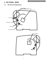
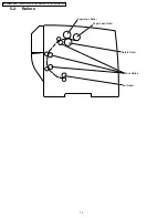
Page 116: ...14 1 Exterior 116 KV S2025C Series KV SU225C Series KV S2045C Series KV SU245C Series ...

Page 117: ...EB0052Z Reflector Sheet 36 PJKEB0071Z Name Card Guide ISO Code PS 37 PJKEB0072Z Name Card Stopper ISO Code PS 38 PJKMB0001Z Base ISO Code PS 39 PJHGB0022Z Rubber Foot 40 PJMCB0077Z Control Board Case 41 PJJTB0020Z Wire Cover Earth 42 PPB662CHS01 CONTROL Board for KV S2025C RTL PbF 42 PPB663CHS01 CONTROL Board for KV S2045C RTL PbF 43 PJJEB2602Z Cable 44 PJJTB0011Z Clamp 45 PJJTB0009Z Clamp 46 PJJT...

Page 118: ...14 2 Chassis and Base 118 KV S2025C Series KV SU225C Series KV S2045C Series KV SU245C Series ...

Page 119: ...1 PJJTB0014Z Cable 42 PPB662SAE03C RELAY BACK Board for KV S2025C RTL PbF 42 PPB663SAE03C RELAY BACK Board for KV S2045C RTL PbF 43 PBMEA0010Z Discharge Brush 44 YMC10 0 V0 Clamp 45 LWS 1S Locking Wire Saddle 46 PLT 1M Cord Clamp for KV S2045C 47 PJJTB0017Z Cable for KV S2045C 48 PJMCB0080Z CIS Cable Shield Plate for KV S2045C 49 TB 1116 Bush 50 TB 2533 Bush 51 PJJTB0002Z Cable 52 PJJTB0003Z Cable...

Page 120: ...14 3 Hopper Unit 120 KV S2025C Series KV SU225C Series KV S2045C Series KV SU245C Series ...

Page 121: ...Plate 30 PJJTB0016Y Cable for KV S2045C 31 PBDGA0061Z Gear ISO Code POM 32 PBDJA0020Z Spacer 33 PJDRB0077Z Sensor Roller B Black 34 PJUEB0024Z Conveyor 5 35 PJMEB0024Z Discharge Brush for KV S2045C 36 PJMEB0025Z Discharge Brush for KV S2045C 37 PJHRB0538Z Conveyor 4 ISO Code PS 38 PJHRB0539Z Conveyor 6 ISO Code PC 39 PPB662SAE03B RELAY FRONT Board for KV S2025C RTL PbF 39 PPB663SAE03B RELAY FRONT ...

Page 122: ...14 4 Power Unit 122 KV S2025C Series KV SU225C Series KV S2045C Series KV SU245C Series ...

Page 123: ...ode PPE 6 PJMCB0078Z Power Board Box 7 PPB662PWU02A POWER Board RTL PbF 8 PJJTB0013Z Cable 9 PJJTB0015Z Cable 10 SG 130 Clamp 11 PJMCB0079Z Power Board Box Cover 12 PJJTB0014Z Cable 13 LWS 1S Locking Wire Saddle 14 LWS 3S Clamper 15 PJHEB0065Z Water Resistant Sheet 133 XTW3 U6LFX Screw 136 XTW3 U8SFX Screw 139 XYN3 F6FX Screw 145 XYN4 F6FXS Screw 123 KV S2025C Series KV SU225C Series KV S2045C Ser...

Page 124: ...14 5 Packing 14 5 1 KV S2025C SU225C Series 124 KV S2025C Series KV SU225C Series KV S2045C Series KV SU245C Series ...

Page 125: ...shion Top L ISO Code PS 6 K2CG3DH00032 Power Cord 120V for Type A 2 7 PBHSA0055Z Roller Cleaning Paper TSCA 8 PBQX70021Z Warranty Card 9 PJQXB0016Z Installation Manual 10 PJQMB0097Z Maintenance Manual 11 PJPPB0009Z Set Cover ISO Code PE 12 PJPNB0104Z Roller Pad 13 PBQX90154Z Notice Paper 14 PJPNB0097Z AC Cord Pad 15 PJPNB0098Z CD ROM Pad 125 KV S2025C Series KV SU225C Series KV S2045C Series KV SU...

Page 126: ...14 5 2 KV S2045C SU245C Series 126 KV S2025C Series KV SU225C Series KV S2045C Series KV SU245C Series ...

Page 127: ...PQB0023Z Cushion Top L ISO Code PS 6 K2CG3DH00032 Power Cord 120V for Type A 2 7 PBHSA0055Z Roller Cleaning Paper TSCA 8 PBQX70021Z Warranty Card 9 PJQXB0016Z Installation Manual 10 PJQMB0097Z Maintenance Manual 11 PJPPB0009Z Set Cover ISO Code PE 12 PJPNB0104Z Roller Pad 13 PBQX90154Z Notice Paper 16 PJPNB0099Z Accessory Box 127 KV S2025C Series KV SU225C Series KV S2045C Series KV SU245C Series ...

Page 128: ... J 1 16W for KV S2045C R1034 ERJ3GEYJ223 22k J 1 16W for KV S2045C R1035 ERJ3GEYJ103 10k J 1 16W for KV S2045C R1036 ERJ3GEYJ272 2 7k J 1 16W R1037 ERJ3GEYJ222 2 2k J 1 16W R1038 ERJ3GEYJ222 2 2k J 1 16W R1039 ERJ3GEYJ103 10k J 1 16W R1040 ERJ3GEYJ103 10k J 1 16W R1041 ERJ3GEY0R00 0 ohm Jumper for KV S2025C R1042 ERJ3GEY0R00 0 ohm Jumper for KV S2025C R1043 ERJ3GEY0R00 0 ohm Jumper for KV S2045C R...

Page 129: ...Description Remarks R1249 ERJ6GEYJ331 330 J 1 10W R1250 ERJ6GEYJ331 330 J 1 10W for KV S2045C R1251 ERJ6GEYJ331 330 J 1 10W for KV S2045C R1276 D4DC71R40001 Poly Switch R1281 ERJ3GEYJ105 1000k J 1 16W for KV S2045C R1282 ERJ3GEYJ104 100k J 1 16W for KV S2045C R1283 SR73K2ETD0 1 Resistor for KV S2045C R1284 SR73K2ETD0 1 Resistor for KV S2045C R1288 ERJ3GEYJ103 10k J 1 16W R1300 ERJ3GEYJ563 56k J 1 ...

Page 130: ...CUX1E104ZFV 0 1 Z 25V C1011 ECEV1AA101SP 100 10V C1013 ECUX1E104ZFV 0 1 Z 25V C1014 ECUV1H101JCV 100p J 50V for KV S2025C Ref No Part No Part Name Description Remarks C1015 ECUX1E104ZFV 0 1 Z 25V C1016 ECUX1E104ZFV 0 1 Z 25V for KV S2045C C1017 ECUX1E104ZFV 0 1 Z 25V for KV S2045C C1018 ECUX1C105ZFW 1 Z 16V for KV S2045C C1019 ECUX1C105ZFW 1 Z 16V for KV S2045C C1020 ECUX1C105ZFW 1 Z 16V for KV S2...

Page 131: ...391 ECUX1E104ZFV 0 1 Z 25V C1392 ECEV1CA100SR 10 16V C1393 ECUX1E104ZFV 0 1 Z 25V C1394 ECEV1CA100SR 10 16V C1411 EEVFC1V470P 47 35V for KV S2045C C1412 EEVFC1V470P 47 35V for KV S2045C C1413 F2DZZ3R30001 Capacitor for KV S2045C C1415 ECUV1H102KBV 1000p K 50V for KV S2045C C1416 ECUX1H473ZFV 0 047 Z 50V for KV S2045C C1417 ECUV1H102KBV 1000p K 50V for KV S2045C C1418 ECUV1H103KBV 0 01 K 50V for KV...

Page 132: ...V for KV S2045C C1598 ECJ1VC1H030C 3p C 50V for KV S2045C C1601 ECUX1E104ZFV 0 1 Z 25V Ref No Part No Part Name Description Remarks C1602 ECUV1H101JCV 100p J 50V for KV S2045C C1604 ECUX1E104ZFV 0 1 Z 25V for KV S2045C C1605 ECUV1H101JCV 100p J 50V for KV S2045C C1606 ECUX1E104ZFV 0 1 Z 25V C1607 ECUV1H101JCV 100p J 50V for KV S2025C C1609 ECUX1E104ZFV 0 1 Z 25V C1610 ECUV1H101JCV 100p J 50V for K...

Page 133: ...tor Q1020 B1ABCF000011 Transistor Q1021 B1ABCF000011 Transistor Ref No Part No Part Name Description Remarks Q1022 B1ABCF000011 Transistor Q1023 B1ABCF000011 Transistor Q1025 B1ABCF000011 Transistor Q1026 B1ABCF000011 Transistor for KV S2045C Q1027 UN2212 Transistor Q1028 B1ABCF000011 Transistor Q1029 B1ABCF000011 Transistor for KV S2045C Q1030 UN2212 Transistor Q1031 B1ABCF000011 Transistor Q1032...

Page 134: ...JL3 0 1 J 50V C853 F2A1A1020038 1000p 10V C871 EEUFC1V471 47 35V C872 F2A1H3300020 33 50V C873 ECFF1H104ZF5 0 1 Z 50V C889 ECFF1H104ZF5 0 1 Z 50V COILS L801 ELF15N010A Line Filter L802 ELF15N010A Line Filter L851 G0A121J00003 Coil Ref No Part No Part Name Description Remarks DIODES D801 B0EBNR000008 Diode D802 B0EAEM000001 Diode D803 B0HAMV000022 Diode D804 B0EAEM000001 Diode D805 B0EAEM000001 Dio...

Page 135: ...9 Connector for KV S2045C CN516 K1MN26A00044 Connector CN517 K1MN20B00088 Connector for KV S2045C Ref No Part No Part Name Description Remarks CN518 K1KA05A00082 Connector 15 8 RELAY BACK Board Ref No Part No Part Name Description Remarks RESISTORS R507 ERDS2TJ331 330 J 1 4W for KV S2045C R508 ERDS2TJ331 330 J 1 4W for KV S2045C R509 ERDS2TJ331 330 J 1 4W for KV S2045C R510 ERDS2TJ331 330 J 1 4W f...

Reviews: