background image

4

Notice

Federal Communications Commission Requirements

                                                    (For United States only)

Note:

This equipment has been tested and found to comply with the limits for a Class A digital device, pursuant to 

part 15 of the FCC Rules. These limits are designed to provide reasonable protection against harmful interference 
when the equipment is operated in a commercial environment. This equipment generates, uses, and can radiate 
radio frequency energy and, if not installed and used in accordance with the instruction manual, may cause harmful 
interference to radio communications. Operation of this equipment in a residential area is likely to cause harmful 
interference in which case the user will be required to correct the interference at his own expense.

For your safety please read the following text carefully.

                                                 (For United Kingdom only)

This appliance is supplied with a moulded three pin mains plug for your safety and convenience.
A 5 amp. fuse is fitted in this plug. Should the fuse need to be replaced please ensure that the replacement fuse has 
a rating of 5 amps. and that it is approved by ASTA or BSI to BS1362. Check for the ASTA mark 

 or the BSI 

mark 

 on the body of the fuse. If the plug contains a removable fuse cover you must ensure that it is refitted when 

the fuse is replaced. If you lose the fuse cover the plug must not be used until a replacement cover is obtained. A 
replacement fuse cover can be purchased from your local Panasonic Dealer.

If the fitted moulded plug is unsuitable for the socket outlet in your home then the fuse should be removed and the 

plug cut off and disposed of safely.

There is danger of severe electrical shock if the cut off plug is inserted into any 13 amp. socket. 

If a new plug is to be fitted please observe the wiring cord as shown below. If in any doubt please consult a qualified 

electrician.

WARNING: 

This appliance must be earthed.

IMPORTANT: 

The wires in this mains lead are coloured in accordance with the following cord.

Green-and-Yellow : Earth

Blue

: Neutral

Brown

: Live

As the colours of the wire in the mains lead of this appliance may not correspond with the coloured markings 

identifying the terminals in your plug, proceed as follows.

The wire which is coloured Green-and-Yellow must be connected to the terminal in the plug which is marked with the 

letter E or by the Earth symbol 

 or coloured Green-and-Yellow.

The wire which is coloured Blue must be connected to the terminal in the plug which is marked with the letter N or 

coloured Black.

The wire which is coloured Brown must be connected to the terminal in the plug which is marked with the letter L or 

coloured Red.

FCC Warning:

 To assure continued FCC compliance, the user must use only shielded interface cable and the 

provided power supply cord. Also, any unauthorized changes or modifications to this equipment would void the 

user’s authority to operate this device.

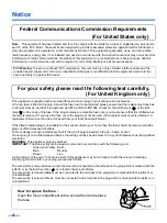
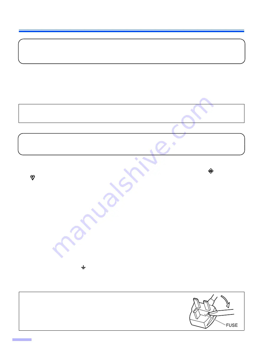
How to replace the fuse :


Open the fuse compartment with a screwdriver and replace 
the fuse.

Summary of Contents for KV S2026C - Document Scanner

Page 1: ...2046C KV S2046CU KV S2046CA These instructions contain information on operating the scanner Before reading these instructions please read the Installation Guide enclosed with this unit Keep the CD ROM in the protective case Do not expose the CD ROM to direct sunlight or extreme heat and do not scratch or smudge the surface of the CD ROM ...

Page 2: ...porated in the United States and or other countries Pentium is a trademark or registered trademark of Intel Corporation or its subsidiaries in the United States and other countries Each company s name or company product name is each company s trademark or registered trademark The information given in these Operating Instructions is subject to change without notice Illegal Duplication It is unlawfu...

Page 3: ...ng paper jams from the feeding section 22 Cleaning the Unit 24 Outside of the scanner 24 Inside the scanner 24 Cleaning the reflector sheet for the ending sensor 24 Cleaning the rollers and sensors 25 Cleaning the CIS glasses and sensor rollers 27 Replacing Consumables 29 Replacing the paper feed roller module 29 Replacing the double feed prevention roller module 32 How to re attach the sensor rol...

Page 4: ...cement fuse cover can be purchased from your local Panasonic Dealer If the fitted moulded plug is unsuitable for the socket outlet in your home then the fuse should be removed and the plug cut off and disposed of safely There is danger of severe electrical shock if the cut off plug is inserted into any 13 amp socket If a new plug is to be fitted please observe the wiring cord as shown below If in ...

Page 5: ...hed and that the installation is completely safe For your safety if in any doubt about the effective grounding earthing of the power point consult a qualified electrician If the plug cannot be inserted into the AC outlet contact a licensed electrician to replace the AC outlet with a properly grounded earthed one Do not defeat the purpose of the grounding earthing plug ex do not use a conversion pl...

Page 6: ... time switch it off and unplug it If an unused unit is left connected to a power source for a long period degraded insulation may cause electric shock current leakage or fire CAUTION Do not position the unit in a location where it is unstable To prevent fire or shock hazard do not expose this unit to rain or any type of moisture Do not place the unit in a hot humid or dusty environment Prolonged e...

Page 7: ...7 KV S2048C KV S2028C KV S2026C S2026CU S2026CA KV S2046C S2046CU S2046CA Caution Labels For Your Safety ...

Page 8: ...ing Paper Do not store the roller cleaning paper in direct sunlight or in a place with temperature over 40 C 104 F Only use the roller cleaning paper to clean the rollers and scanning area If you need more information about the roller cleaning paper please refer to the Material Safety Data Sheet MSDS Please ask your Panasonic sales company about obtaining the Material Safety Data Sheet KEEP AWAY F...

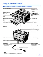
Page 9: ...siness card stopper Exit tray Exit stopper ADF door ADF door release STOP START button LED Radiation vent Power switch Business card guides Imprinter door for KV S2048C only AC inlet Power cord Plugs vary in shape among countries USB connector SCSI connectors for KV S2026C S2026CU S2026CA only Imprinter door pull for KV S2048C only Imprinter door for KV S2048C only DIP switch for KV S2026C S2026CU...

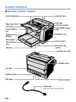
Page 10: ... tray Business card stopper Exit extension tray Exit stopper Imprinter door ADF door ADF door release STOP START button LED Radiation vent Power switch Business card guides Exit tray DIP switch AC inlet SCSI connectors Imprinter door pull Imprinter door USB connector Power cord Plugs vary in shape among countries ...

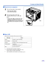
Page 11: ...owered on even after the host computer is powered on About LED LED indicates the status of the scanner as follows 1 The rollers need to be cleaned or replaced 1 2 Check the status of the scanner using the User utility The User utility is included in the CD ROM 3 With KV S2048C and KV S2028C the LED blinks in green LED light Status Green Ready to scan or scanning Green Blink Sleep mode Orange Ready...

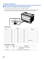
Page 12: ...correctly The scanner is provided with a DIP switch for the SCSI ID No setting and the terminator setting SCSI ID Setting SCSI Terminator Setting ID No Switch Remarks 2 1 0 0 OFF OFF OFF 1 OFF OFF ON 2 OFF ON OFF 3 OFF ON ON 4 ON OFF OFF 5 ON OFF ON 6 ON ON OFF Default setting 7 ON ON ON Function Switch Description Enable ON The last device in the SCSI chain Default setting Disable OFF Not the las...

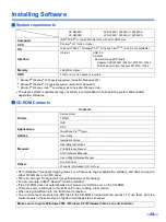
Page 13: ...o the ISIS driver is required The control sheets are stored as PDF files in the CD ROM provided with the scanner For use them print the control sheets in the same size as the document pages to be scanned KV S2048C KV S2028C KV S2046C S2046CU S2046CA KV S2026C S2026CU S2026CA Computer IBM PC AT or compatible machine with a CD ROM drive CPU Pentium III 1GHz or higher OS Windows 2000 1 Windows XP 2 W...

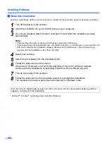
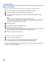
Page 14: ...ion software double click on CDRun exe in the root directory to manually start the installation routine then click OK 4 Select your scanner 5 Select the Complete from the Installation list 6 Follow the instructions on the screen If the screen Windows can t verify the publisher of this driver software appears continue with the installation by selecting Install this driver software anyway 7 Turn on ...

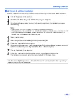
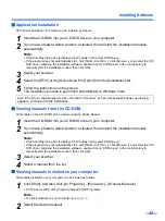
Page 15: ...ve containing the installation software double click on CDRun exe in the root directory to manually start the installation routine then click OK 4 Select your scanner 5 Select the All Drivers Utilities from the Installation list 6 Follow the instructions on the screen If the screen Windows can t verify the publisher of this driver software appears continue with the installation by selecting Instal...

Page 16: ...re double click on CDRun exe in the root directory to manually start the installation routine then click OK 4 Select your scanner 5 Select the Custom from the Installation list 6 Select a driver an utility or a manual If the screen Windows can t verify the publisher of this driver software appears continue with the installation by selecting Install this driver software anyway 7 Follow the instruct...

Page 17: ... the CD ROM can be viewed using the Adobe Reader 1 Insert the CD ROM into your CD DVD drive on your computer 2 If you have a feature called Autorun activated this will start the installation process automatically Note If the AutoPlay dialog box is displayed in Windows Vista select CDRun exe If the program does not automatically start click Start click Run click Browse and select the CD DVD drive c...

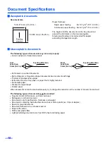
Page 18: ... paper Extremely smooth shiny paper or paper that is highly textured Carbonless paper Creased or ripped paper Coated paper When documents cannot be scanned properly try to change the resolution or the number of documents scanned The following types of documents must be avoided Irregular document thickness such as envelopes Damaged or notched document Documents out of specified size thickness and w...

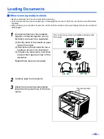
Page 19: ...that have been stapled together or stacked together as in a file folder will need to be separated 1 Fan the stack of documents to sepa rate all the edges 2 Hold both ends and bend the docu ments as shown in the illustration 3 To flatten the documents hold firmly and pull them apart as shown in the illustration Repeat these steps as necessary 2 Carefully align the documents 3 Adjust the document gu...

Page 20: ...es and the business card stopper Caution Do not use the business card guides and the business card stopper for larger documents than their acceptable size It will cause paper jams 5 Place the documents on the feed tray with the side to be scanned facing up Be sure to place the documents on the feed tray as shown in the figure on the right The amount of documents should not exceed the limit mark on...

Page 21: ...size of the documents 7 Set documents under the paper feed roller 1 Lift the lever of the paper feed roller as shown in the figure 2 Push documents in the direction of the arrow until they stop under the paper feed roller Document guides 1 2 Paper feed roller ...

Page 22: ...med sheet according to the following procedure Removing paper jams from the feeding section 1 Remove all documents from the feed tray 2 Push the ADF door release to open the ADF door 3 Remove the jammed document If the jammed document remains at the feed tray side pull it up If the jammed document appears at the exit tray side remove it from the exit side ...

Page 23: ...ollers are installed properly before closing the ADF door If the sensor rollers are removed re attach them Refer to page 34 5 Close the ADF door When you close the ADF door close it securely until the door is locked Sensor roller front Sensor roller back ...

Page 24: ...irst Clean the rollers and sensors if paper jamming or multiple sheet feeding occurs frequently Refer to pages 25 26 Clean the CIS glasses and sensor rollers when lines appear on the scanned images Refer to pages 27 28 If the documents you scan are dirty then the scanner components will also become dirty To maintain proper scanning clean the scanner components frequently Cleaning the reflector she...

Page 25: ...ease use the roller cleaning paper immediately after opening the bag Before using the roller cleaning paper please read the safety information on the Operation Manual enclosed with the roller cleaning paper The roller cleaning paper Model No KV SS03 is available from the dealer where you purchased your scanner For supplies and accessories Call 1 866 823 0002 U S A only or your dealer 1 Turn the po...

Page 26: ...re on the right 4 Make sure that the sensor rollers are installed properly before closing the ADF door If the sensor rollers are removed re attach them Refer to page 34 5 Close the ADF door When you close the ADF door close it securely until the door is locked 6 Clear the roller cleaning counter with the User Utility After the rollers have been cleaned press the Clear Counter button in the User Ut...

Page 27: ...Cleaning the Unit 27 Cleaning the CIS glasses and sensor rollers 1 Turn the power off 2 Push the ADF door release to open the ADF door ...

Page 28: ...ler cleaning paper If the sensor rollers are removed while cleaning re attach them after cleaning 4 Close the ADF door When you close the ADF door close it securely until the door is locked Sensor roller front CIS glass back CIS glass front Sensor roller back Sensor roller front ...

Page 29: ...F door release to open the ADF door 3 Push the two green levers down at both ends of the paper feed roller mod ule to unlock the paper feed rollers When moving the green levers do not apply pressure in any other direction other than in the direction shown by the arrows Otherwise the levers may break ...

Page 30: ...he new paper feed roller mod ule with its gear on the right 1 Hang both ends of the paper feed roller module 2 While slightly lifting the paper feed roller module pass the claw along the groove of the feed cover 3 Attach the bearings at both ends of the paper feed roller module into the guide grooves of the chassis in the scanner Claw Paper feed case Groove Green levers Chassis Bearings ...

Page 31: ... the direction of the arrows until they click into place After installing the paper feed roller mod ule confirm that the feed rollers can be moved lightly in vertical direction 7 Close the ADF door When you close the ADF door close it securely until the door is locked ...

Page 32: ...le 1 Turn the power off 2 Push the ADF door release to open the ADF door 3 Remove the double feed prevention roller cover 4 Remove the double feed prevention roller module in the direction of the arrow Double feed prevention roller cover Double feed prevention roller module ...

Page 33: ...e holder 6 Close the double feed prevention roller cover 7 Close the ADF door When you close the ADF door close it securely until the door is locked 8 Clear the roller replacing counter with the User Utility After the rollers have been replaced press the Clear Counter button in the User Utility to clear the After Replace Roller counter to zero Refer to the User Utility Reference Manual Wider groov...

Page 34: ...release Match the groove to the guide Push the roller and confirm the sensor is locked by the springs on both sides Re attach the sensor roller for front scanning Attach the longer roller to the unit by placing the non gear side to the ADF door release Match the groove to the guide Attach the side of the ADF door release first and attach the other side Confirm both rollers move slightly Press down...

Page 35: ...ing adjustment Before proceeding be absolutely sure to thoroughly clean the CIS glasses transport path drive rollers free rollers and sensor rollers using the roller cleaning paper If the shading adjustment is carried out while these parts are still dirty it will not be possible to eliminate the lines that form on the scanned images z Shading adjustment procedure 1 Start the User Utility 2 Click U...

Page 36: ...pair the unit The scanner should be handled in the correct horizontal position Materials Required Original Scanner Carton Packing Materials Shipping Tape and Scissors 1 Turn the power switch off and disconnect your scanner from the electrical outlet and the interface cable 2 Return the feed extension tray exit stopper and exit extension tray to their original posi tions 3 Pack the scanner Power co...

Page 37: ... The scanner should be handled in the correct horizontal position Materials Required Original Scanner Carton Packing Materials Shipping Tape and Scissors 1 Turn the power switch off and disconnect your scanner from the electrical outlet and the interface cable 2 Remove the feed extension tray and exit extension tray 3 Pack the scanner Power cord Be sure to use a power cord whose shape matches the ...

Page 38: ...n Note Dither and Error diffusion are executed by driver software or RTIV Image control Image emphasis 5 step Dynamic threshold Automatic separation Noise reduction Deskew Cropping Mirror image Monochrome reversing Gamma correction Note These all functions are executed by driver software or RTIV Other function Patch code detection Kodak patch 2 3 T Note 1 portion both side each executed only by IS...

Page 39: ... 19 0 lbs 8 5 kg 18 7 lbs Power requirement AC100 120 V 50 60 Hz AC220 240 V 50 60 Hz Power consump tion Maximum Scanning 1 A AC100 120 V 0 5 A AC220 240 V Minimum Standby 0 3 A AC100 120 V 0 2 A AC220 240 V 0 35 A AC100 120 V 0 2 A AC220 240 V 0 3 A AC100 120 V 0 2 A AC220 240 V Sleep mode 3 5 W AC100 120 V 6 W AC220 240 V 6 W AC100 120 V 8 W AC220 240 V 3 5 W AC100 120 V 6 W AC220 240 V 6 W AC10...

Page 40: ...canner is the last device in the SCSI chain set the DIP switch of SCSI terminator to Enable If the scanner is not the last device in the SCSI chain set the DIP switch of SCSI terminator to Disable The scanner was turned on after the computer was turned on Turn the computer OFF Turn the scan ner ON and then turn the computer ON again USB connection The USB interface of the computer is not installed...

Page 41: ...rectly See page 19 Vertical lines appear on the scanned document The CIS glasses are dirty Clean the CIS glasses See page 27 The sensor rollers are dirty Clean the sensor rollers See page 27 The scanning density is uneven The CIS glasses or the sensor rollers are dirty Clean the CIS glasses and the sensor rollers See page 27 The color of the scanned document is extremely different from the origina...

Page 42: ...cation 9 Custom installation 16 D DIP switch 9 10 12 Document guides 9 10 19 Double feed detection 38 Double feed detector 26 Double feed prevention roller 26 Double feed prevention roller cover 32 Double feed prevention roller module 32 Drive rollers 26 E ENERGY STAR 2 Exit extension tray 9 10 20 Exit stopper 9 10 20 Exit tray 9 10 External dimensions 39 F Feed extension tray 9 10 20 Feed tray 9 ...

Page 43: ...er module 32 Resolution 38 Roller cleaning paper 25 28 Roller exchange kit 39 S Scanning face 38 Scanning method 38 Scanning speed 38 SCSI connectors 9 10 SCSI setting 12 SCSI terminator 12 Sensor rollers 23 28 34 Separation roller 26 Shading adjustment 35 Specifications 38 Starting position sensor 26 STOP START button 9 10 Storage temperature and humidity 39 T Tonal gradation 38 Troubleshooting 4...

Page 44: ...anasonic U K Ltd Willoughby Road Bracknell Berkshire RG12 8FP Panasonic Marketing Europe GmbH Hagenauer Strasse 43 65203 Wiesbaden Germany For information of Compliance with EU relevant Regulatory Directives Contact Panasonic Testing Centre Panasonic Services Europe a Division of Panasonic Marketing Europe GmbH Winsbergring 15 22525 Hamburg Germany Matsushita Electric Industrial Co Ltd http panaso...

Reviews: