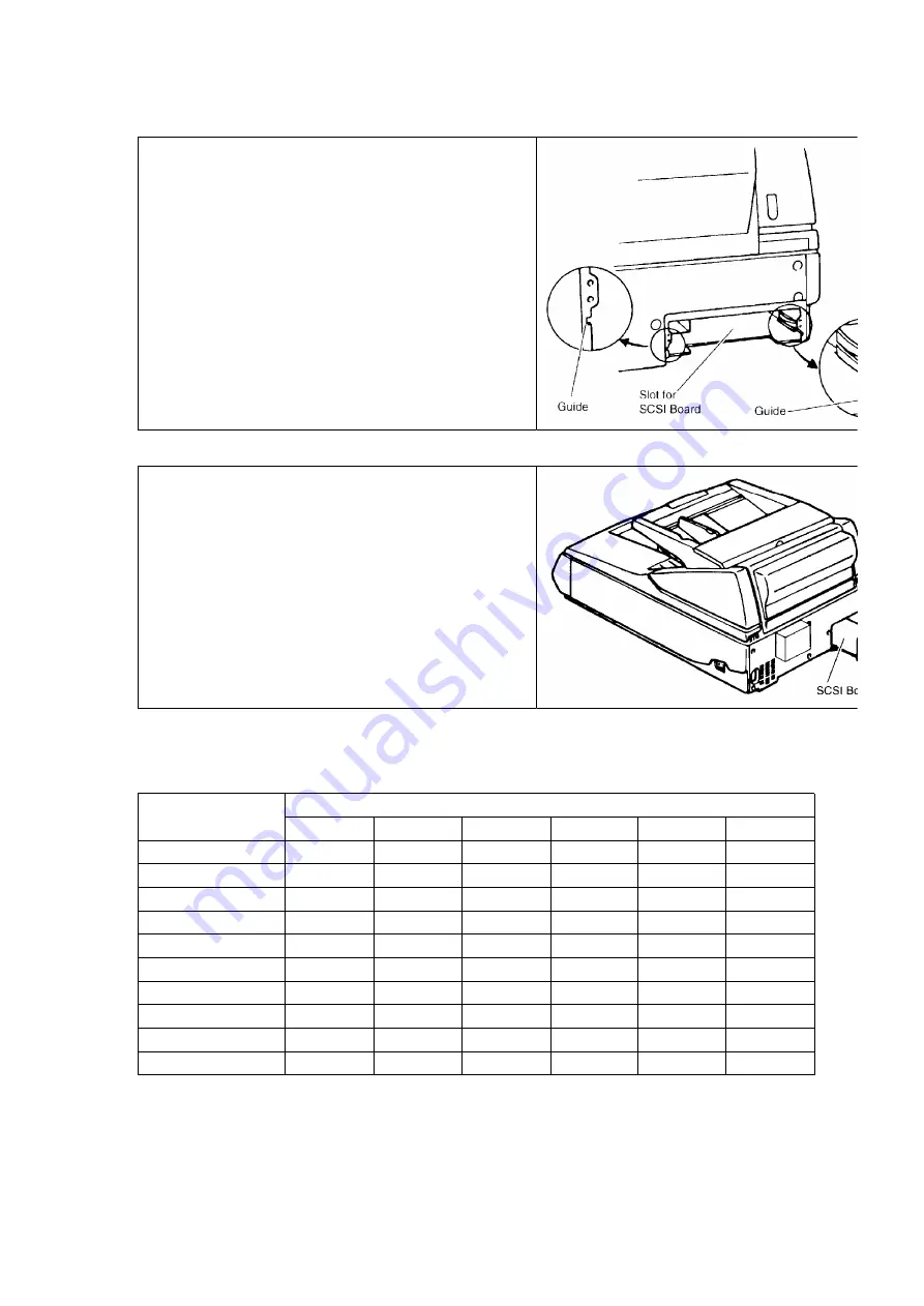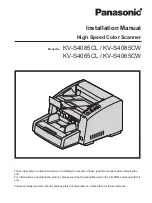
1) Insert the SCSI Board into the unit along the
guides and push it in firmly.
2) Secure the SCSI Board with the 3 screws.
3) Install the scanner driver software in your
computer according to the enclosed manuals.
4.6.1. Additional Memory Size each scanning mode ( MB )
Simplex/4bit, 8bit
Size
Resolution (dpi)
100
200
300
400
500
600
A3
0
0
64
64
64
128
A4
0
0
0
0
64
64
A5
0
0
0
0
0
64
A6
0
0
0
0
0
0
B4 (JIS)
0
0
0
64
64
64
B5 (JIS)
0
0
0
0
64
64
B6 (JIS)
0
0
0
0
0
0
Double Letter
0
0
64
64
64
128
Legal
0
0
0
64
64
64
Letter
0
0
0
0
64
64
Duplex/4bit, 8bit
7
Summary of Contents for KV-S6055W
Page 24: ...Fig 7 8 24 ...
Page 35: ...8 2 14 Sensor Plate 1 Open Front Door 2 Loosen 2 screws 3 Remove Sensor Plate Fig 8 18 35 ...
Page 50: ...Fig 8 42 8 3 15 ADF Door Switch 50 ...
Page 84: ...11 BLOCK DIAGRAM 84 ...
Page 88: ...15 1 Exterior 88 ...
Page 92: ...REPALCEMENT MECHANICAL PARTS LIST Hopper Unit 92 ...
Page 102: ...REPLACEMENT MECHANICAL PARTS LIST Packing 102 ...
Page 130: ......
Page 131: ......
Page 132: ......
Page 133: ......
Page 134: ......
Page 135: ......
Page 136: ......
Page 137: ......
Page 138: ......
Page 139: ......
Page 140: ......
Page 167: ......
Page 184: ...Pin No Signal Name Description Pin No Signal Name Description Pin No Signal Name Description ...
Page 231: ......
Page 233: ... Component Side Solder Side ...
Page 235: ......
Page 236: ......
Page 237: ......
Page 238: ......
Page 239: ......
Page 240: ......
Page 241: ......
Page 243: ......
Page 244: ......
Page 245: ......
Page 246: ......
Page 247: ......
Page 248: ......
Page 250: ......
Page 251: ......
Page 254: ... Component Side Solder Side ...
Page 256: ......
Page 258: ......
Page 261: ......
Page 262: ......
Page 263: ......
Page 264: ......
Page 265: ......
Page 266: ......
Page 267: ......


