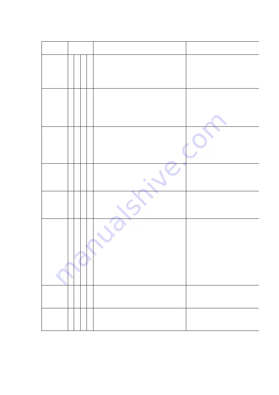
Classified
Code
Error
Code
Possible Cause
Check Point
U10
10 00 00 00 Paper Detector does not work.
1. Paper has not been properly set.
2. The back side of the last scanning is black.
3. A connector for the sensor signal is loosen.
4. Paper Detector is damaged.
1. Replace the torn or ripped paper.
2. Place correct sheet.
3. Confirm operation of the sensor in Test Mode.
sensor does not work, the connector has come
Attach the connector correctly.
4. Check whether the cable and/or Sensor board
broken.
U11
11 xx 00 00 Paper does not feed in the correct timing.
1. Slip caused by dirt of the roller.
2. Conveyor has not been set properly.
3. Double Feed.
4. Sensor error.
1. Replace the Paper Feed Roller, Separation Roller,
Retard Roller if they are worn down.
2. Set conveyor properly.
3. Clean the Separation Roller and Retard Roller.
whether the Retard Roller is properly set. Replace
Paper Feed Roller, Separation Roller, or Retard
they are worn down.
4. Clean any paper dust on the sensor section.
U12
12 xx 00 00 Paper does not reach to the Starting
Position Sensor.
1. Paper Feed Roller, Separation Roller, and Retard Roller
are slipping.
2. Following Paper which cause Double Feed is left,
inside unit.
3. Sensor error.
1. Clean the Paper Feed Roller, Separation Roller,
Retard Roller.
2. Clean the Separation Roller and the Retard
3. Clean any paper dust on the sensor section.
U13
13 xx 00 00 Paper does not reach to the Ending
Position Sensor.
1. Slip caused by dirt of the roller.
2. Sensor error.
3. Conveyor has not been properly installed.
1. Clean the Conveyor Roller.
2. Clean any paper dust on the sensor section.
3. Assemble the conveyor properly.
U16
16 xx 00 00 Paper does not pass the Ending Position
Sensor.
1. Slip caused by dirt of the roller.
2. Sensor error.
3. Conveyor has not been properly installed.
1. Clean the Conveyor Roller.
2. Clean any paper dust on the sensor.
3. Assemble the conveyor properly.
U18
18 xx 00 00
1. Paper remains in the equipment.
2. The Paper Detector is ON.
(1) LED is broken.
(2) Sensor is broken. Confirm the LED and the sensor
operation state.
Confirm steps:
1) Start the Doc Sensor Test in Test Mode.
2) Open the conveyor and shine a light on the
sensor. If the sensor turns ON, there is a problem
with the LED. If the sensor does not turn ON,
there is a problem with the sensor.
(3) Conveyor is not assembled correctly.
(4) LED or Sensor is bent down.
(5) Sensor is covered with paper dust.
1. Remove paper.
2. (1) Replace the LED.
(2) Replace the Sensor.
(3) Assemble the conveyor properly.
(4) Replace the LED or sensor.
(5) Clean any dust on the sensor section.
U30
20 00 00 00 U30 Error Code does not turn off even
through the Front Door is closed.
1. Front Door Switch is not being correctly shut down.
2. Front Door Switch is broken.
1. Check that the Front Door Switch is not being
correctly shut down.
2. Replace the Front Door Switch.
U31
21 00 00 00 U31 Error Code does not turn off even
through the ADF Door is closed.
1. ADF Door Switch is not being correctly shut down.
2. ADF Door Switch is broken.
1. Check that the ADF Door Switch is not being
shut down.
2. Replace the ADF Door Switch.
80
Summary of Contents for KV-S6055W
Page 24: ...Fig 7 8 24 ...
Page 35: ...8 2 14 Sensor Plate 1 Open Front Door 2 Loosen 2 screws 3 Remove Sensor Plate Fig 8 18 35 ...
Page 50: ...Fig 8 42 8 3 15 ADF Door Switch 50 ...
Page 84: ...11 BLOCK DIAGRAM 84 ...
Page 88: ...15 1 Exterior 88 ...
Page 92: ...REPALCEMENT MECHANICAL PARTS LIST Hopper Unit 92 ...
Page 102: ...REPLACEMENT MECHANICAL PARTS LIST Packing 102 ...
Page 130: ......
Page 131: ......
Page 132: ......
Page 133: ......
Page 134: ......
Page 135: ......
Page 136: ......
Page 137: ......
Page 138: ......
Page 139: ......
Page 140: ......
Page 167: ......
Page 184: ...Pin No Signal Name Description Pin No Signal Name Description Pin No Signal Name Description ...
Page 231: ......
Page 233: ... Component Side Solder Side ...
Page 235: ......
Page 236: ......
Page 237: ......
Page 238: ......
Page 239: ......
Page 240: ......
Page 241: ......
Page 243: ......
Page 244: ......
Page 245: ......
Page 246: ......
Page 247: ......
Page 248: ......
Page 250: ......
Page 251: ......
Page 254: ... Component Side Solder Side ...
Page 256: ......
Page 258: ......
Page 261: ......
Page 262: ......
Page 263: ......
Page 264: ......
Page 265: ......
Page 266: ......
Page 267: ......


