background image

© Panasonic Communications Co., Ltd. 2008  Unau-
thorized copying and distribution is a violation of law.

Order Number KM70811446CE

Category Number H19

Flatbed Scanner

Model No.

KV-SS080

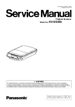
Summary of Contents for KV-SS080

Page 1: ... Panasonic Communications Co Ltd 2008 Unau thorized copying and distribution is a violation of law Order Number KM70811446CE Category Number H19 Flatbed Scanner Model No KV SS080 ...

Page 2: ...EWS 15 5 1 Flatbed Block and Boards 15 6 MECHANICAL FUNCTION 16 6 1 Carriage Drive Mechanism 16 7 MAINTENANCE 17 7 1 Maintenance 17 7 2 Cleaning 17 8 DISASSEMBLY INSTRUCTIONS 19 8 1 Disassembly Flowchart 19 8 2 Disassembling 20 9 SERVICE UTILITY SELF TEST 29 9 1 Main Menu Indication for Service Utility 29 9 2 List of Functions for Service Utility 30 9 3 Operation 31 10 TROUBLESHOOTING 35 10 1 Trou...

Page 3: ...arts with aluminum foil 2 Ground the soldering irons 3 Use a conductive mat on the worktable 4 Do not grasp IC or LSI pins with bare fingers 1 4 About Lead Free Solder PbF Pb free Note In the information below Pb the symbol for lead in the periodic table of elements will refer to standard solder or solder that contains lead We will use PbF when discussing the lead free solder used in our manufactu...

Page 4: ...azardous substances RoHS in electrical and electronic equipment effective 1st July 2006 in the EU countries In order for the product to comply with the RoHS Directive the six particular substances lead mercury cadmium hexavalent chromium polybrominated biphenyls and polybrominated diphenyl ethers have been either totally eliminated or limited to the concentration level below maximum allowed Conseq...

Page 5: ...0 60 Hz AC Adaptor Power consumption Maximum Scanning 0 35 A AC 100 V to 120 V 2 0 2 A AC 220 V to 240 V 3 Minimum Standby 0 25 A AC 100 V to 120 V 2 0 15 A AC 220 V to 240 V 3 Sleep Mode 3 5 W or less AC 100 V to 120 V 2 3 5 W or less AC 220 V to 240 V 3 When the Power Switch is OFF 0 3 W or less AC 100 V to 120 V 2 0 3 W or less AC 220 V to 240 V 3 Environment Operating Temperature and Humidity ...

Page 6: ...st computer operating environment and applications used Model Area Serial No Power Cord KV SS080 USA B15 xxxx xxxx For 100 to 120 V KV SS080 U Europe Russia B16 xxxx xxxx For 220 to 240 V KV SS080 A Australia B17 xxxx xxxx For 220 to 240 V KV SS080 K Korea B18 xxxx xxxx For 220 to 240 V KV SS080 CN China B20 xxxx xxxx For 220 to 240 V KV S080 T Taiwan B19 xxxx xxxx For 100 to 120 V ...

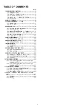
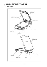
Page 7: ...7 3 COMPONENT IDENTIFICATION 3 1 Part Names ...

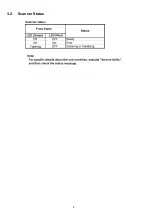
Page 8: ...8 3 2 Scanner Status ...

Page 9: ...9 4 INSTALLATION 4 1 Minimum Space Requirements Be sure to maintain the recommended space requirements for proper ventilation ...

Page 10: ...10 4 2 Unlocking Carriage Lock 1 Remove all packing tape 2 Open the Document Cover 3 Slide the LOCK UNLOCK Selector in the direction of the arrow to release the Carriage lock 4 Close the Document Cover ...

Page 11: ...f the arrows to remove the cover 2 Turn over the Document Cover Carefully push the edge of the Flatbed Sheet nearest to the hinges in the direction of the arrow and confirm that both sides of the sheet are released from the hooks on the cover 3 Lift the Flatbed Sheet slightly in the direction of the arrow 1 and then pull the sheet in the direction of the arrow 2 to remove it ...

Page 12: ...sure that the side edges of the sheet are inserted under the hooks on the Document Cover 5 Turn over the Document Cover and then attach the cover onto the unit making sure to align the hinges with the hinge mounting holes and to re insert the hinges into place ...

Page 13: ...the AC Adaptor and the USB Cable to the back of the unit Caution 1 Only use the Power Cord AC Adaptor and USB Cable included with this scanner 2 Be sure to connect the scanner directly to the USB interface port on the PC We cannot guarantee that the scanner will work properly if it is connected to a USB hub ...

Page 14: ...operating system 3 Windows XP refers to Microsoft Windows XP operating system 4 Windows Vista refers to Microsoft Windows Vista operating system 5 Microsoft Windows and Windows Vista are either registered trademarks or trademarks of Microsoft Corporation in the United States and or other countries 6 Pentium is a trademark of Intel Corporation in the U S and other countries 7 All other trademarks i...

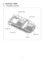
Page 15: ...15 5 SECTIONAL VIEWS 5 1 Flatbed Block and Boards ...

Page 16: ... is issued from the PC the controller confirms its default position and then the Carriage Motor rotates to drive the Scanning Unit 2 After the carriage moves to the specified area according to scanning instructions sent from the PC the Carriage Motor rotates in reverse and the Scanning Unit returns to its home position ...

Page 17: ...s have been scanned whichever comes first 1 Flatbed Glass Top Cover Assy 2 Flatbed Sheet Note The maintenance schedule was determined according to paper standards which can vary greatly between users Therefore the schedule may vary by user 7 2 Cleaning 1 Turn off the scanner 2 Open the Document Cover ...

Page 18: ...lass and Flatbed Sheet with a damp cloth that has been thoroughly wrung Note Use a neutral kitchen cleaner diluted with water for hard to clean stains Do not use thinner benzine or cleaners containing abra sives as this may result in discoloration ...

Page 19: ...oard assemblies When reassembling perform the steps in the reverse order unless otherwise instructed in the Reassembling Notes Note After reassembling all parts constituted make sure that the LOCK UNLOCK Selector is set to UNLOCK Then after turning on the scanner make sure that the Scanning Unit goes back to the default home position and the LED Green on the Panel Cover lights ...

Page 20: ...20 8 2 Disassembling 8 2 1 Document Cover 1 Lift the Document Cover in the direction of the arrows to remove the cover ...

Page 21: ...he 6 screws b and then release the Hinge Assy L from the Document Cover Note Hinge Assy Hinge Assy R Only used for the right side Hinge Assy L Only used for the left side 1 Remove the Document Cover See 8 2 1 2 Remove the 6 screws b and then release the Hinge Assy R from the Document Cover ...

Page 22: ... Note Following this section when proceeding to disassembling the parts mounted to the Bottom Cover Assy be sure to cover the top surface of the Scanning Unit so as to prevent screws or other foreign material from falling into the unit 1 Remove the Top Cover Assy See 8 2 4 2 Turn over the Top Cover Assy and then remove the 2 screws a 3 While pushing down the center of the Panel Cover release the 3...

Page 23: ...ee 8 2 5 2 Unlock the hooks to release the Panel LED Cover from the Panel Cover 1 Remove the Top Cover Assy See 8 2 4 2 While releasing the 2 hooks from the guides in the direction of the arrows pull the Start Button to carefully release the button from the Top Cover Assy ...

Page 24: ...24 8 2 8 PANEL Board 1 Remove the Top Cover Assy See 8 2 4 2 Remove the 2 screws a and 1 connector ...

Page 25: ...lock Selector in the direction of the arrows 1 push the selector in the direction of the arrow 2 to remove it 1 Remove the Top Cover Assy See 8 2 4 2 Remove the 4 screws e and disconnect all connectors on the CONTROL Board 1 Remove the Top Cover Assy See 8 2 4 2 Remove the 3 screws a 1 screw a with washer and 1 screw c 3 Disconnect the 1 connector ...

Page 26: ...e the screw d and 2 screws c 4 Remove the spring to release the Tension Plate Assembly from the scanner Reassembling Note How to assemble the spring 1 Hang one side of the spring to the guide of the Bottom Cover Assy 2 Hang the other side of the spring to the guide on the bottom of plate through the hole of the plate ...

Page 27: ... See 8 2 11 2 Remove the 2 screws c 3 Pull out the Shaft carefully through the hole in the Scanning Unit in the direction of the arrow to separate the shaft from the Bottom Cover Assy 1 Remove the Shaft See 8 2 13 2 Disconnect the connector to the CONTROL Board ...

Page 28: ...s in the reverse order in Sec 8 2 13 8 2 14 and 8 2 15 to reassemble the Drive Belt Scanning Unit and Shaft 2 Reattach the Motor Assy in the reverse order in Sec 8 2 11 and then reattach the Drive Belt to the pulley on the Tension Plate Assembly 3 Loosen the 2 screws c and screw d again so that the belt tension increases on its own 4 Tighten the 2 screws c and screw d ...

Page 29: ...canner Executing ServiceUtility exe will allow you to operate all the functions found in this service utility software Note Be sure to connect only one scanner KV SS080 to a PC so that the main menu operation for KV SS080 is displayed on the PC This utility software is not included with the scanner Please call service or technical support to obtain the utility software This software should be used...

Page 30: ...ndicate scanner information such as Model and Flatbed condition Enable Disable 2 Scanner Condition Sleep Mode Used to set Waiting Time before the scanner enters Sleep Mode 1 Test Flatbed LED Used to flash the indicators on the Front Panel 3 Sleep Used to check whether the sleep mode function works properly 3 Start Button Used to do Start Button ON OFF test 3 Carriage Drive 1 Used to check Carriage...

Page 31: ...resentative 010 Carriage home sensor error F52 System error occurred in Flatbed Scanner Please consult with a service representative 176 Carriage could not go back to the default position F61 System error occurred in Flatbed Scanner Please consult with a service representative 007 White Dark calibration error F62 System error occurred in Flatbed Scanner Please consult with a service representative...

Page 32: ...rror U90 B1 00 00 00 Carriage is locked when starting to scan U91 B3 00 00 00 Carriage lock is detected during initializing scanner F11 AC 00 00 00 Sent data time out error F12 AD 00 00 00 Read data time out error F21 04 00 00 00 RAM Read Write error F51 0A 00 00 00 Carriage home sensor error F52 B0 00 00 00 Carriage could not go back to the default position F61 07 00 00 00 White Dark calibration ...

Page 33: ...ble 9 3 4 Scanner Condition Item Operation Default Remarks Sleep Mode 1 Click Sleep Mode on the main menu Service Utility 2 Set Waiting Time Unit minutes to specify the amount of time until the scanner enters the sleep mode 15 minutes For returning back to the Ready Mode during the Sleep Mode execute Sleep Mode for Test 9 3 5 on the main menu and then click STOP on the Sleep Mode dialog box ...

Page 34: ... as to confirm that the scanner enters the Sleep mode by the lamp s in the Scanning Unit going out Start Button 1 Click Flatbed Test on the main menu 2 Click Start Button on the Flatbed Test dialog box 3 After confirming the indication on the display push the Start Button on the front panel of the unit and check the result on the display that shows Button ON was detected if successful 4 Click Clos...

Page 35: ...s the USB connection 3 Check the soldering condition especially JP5 ASIC and their surrounding circuits on the CONTROL Board Defects in the scanned image ex black or white lines or banding in the image 1 Dust on the Flatbed Glass 1 Clean the surface of the Flatbed Glass 2 Execute Carriage Drive in Sec 9 3 5 to check the scanned image 2 Dust on the scanning position on the Scanning Unit 1 Remove th...

Page 36: ...on in Sec 9 3 5 to check the ON OFF condition 2 Button s ON OFF condition cannot be received by the control circuits on the CONTROL Board 1 Check the following connection and soldering condition on each connector JP4 CONTROL Board to JP1 PANEL Board 2 Check the soldering condition of the switch on the PANEL Board 3 Check the soldering condition of ASCI and its surrounding circuits on the CONTROL B...

Page 37: ...on on each connector CN2 CONTROL Board to CN1 CCD Board 4 Check the soldering condition of ASIC and its surrounding circuits on the CONTROL Board 5 Replace faulty parts U91 Carriage lock is detected during initializing scanner B3 00 00 00 1 Lock Unlock Selector is set to Lock 1 Set the Lock Unlock Selector to Unlock 2 Execute Carriage Drive in Sec 9 3 5 to check whether this error message is clear...

Page 38: ...0 00 1 Carriage feed mechanism has some problems 1 Restart the scanner and then execute Carriage Drive in Sec 9 3 5 to check whether this phenomenon is reproduced 2 Check the mechanical condition of the belt and gears on the Motor Assy 3 Check the belt tension controlled by the Tension Plate Assy 4 Check the Shaft for the carriage is properly assembled 5 Replace faulty parts 2 Motor drive signals ...

Page 39: ...tly Carriage Home Sensor Continuously OFF 1 Execute Carriage Drive in Sec 9 3 5 to check whether this phenomenon is reproduced 2 Check the soldering condition of the sensor and its surrounding circuits on the CCD board of the Scanning Unit 3 Check the following connection and soldering condition on each connector CN2 CONTROL Board to CN1 CCD Board 4 Check the soldering condition of ASIC and its su...

Page 40: ...oduced 2 Check the soldering condition of ASIC JP5 and their surrounding circuits on the CONTROL Board 3 Replace the CONTROL Board 2 The result of the calibration is not correctly transmitted to PC 1 Re connect the USB cable to the scanner and then restart the scanner to confirm whether the same error occurs 2 Replace the USB cable 3 The power supply to the circuit on the CONTROL Board was interru...

Page 41: ...d then execute Carriage Drive in Sec 9 3 5 to check whether the same phenomenon is reproduced 2 Check the following connection and soldering condition on each connector 1 JP1 CCD Board to LED Lamp 2 CN1 CCD Board to CN2 CONTROL Board 3 JP2 CONTROL Board to AC Adaptor 3 Replace faulty parts 2 The Scanning Unit does not work properly 1 Check the following connection and soldering condition on each c...

Page 42: ...als from the CONTROL Board are not transmitted to the Carriage Motor 1 Check the following connection and soldering condition on each connector 1 JP3 CONTROL Board to Carriage Motor 2 JP2 CONTROL Board to AC Adaptor 2 Replace faulty parts 3 Scanner is not be put on a horizontal level area Set the scanner on a horizontal level area F67 Scanner can t find the reference mark B7 00 00 00 The scanning ...

Page 43: ... that the series of scanning processes start The CCD block will scan the pixel data analog signals R G B from the documents and then transmits the data to AFE Block through three channels R G and B The AFE Block will convert the pixel data analog signals R G B into the digital data The converted digital data is stored to the SDRAM controlled by the ASIC After the ASIC finishes processing the digit...

Page 44: ...44 11 2 Block Diagram 2 Board ...

Page 45: ...otor phase A 2 OUT1A Motor phase A 3 OUT2A Motor phase B 4 OUT2B Motor phase B JP4 CONTROL Board JP1 PANEL Board Pin No Signal Name Description JP4 JP1 1 1 Hotkey3 Press Key signal 2 2 DGND Digital Ground 3 3 VCC 5 V power 4 4 VCC 5 V power 5 5 G_FB Green LED feedback circuit 6 6 R_FB RED LED feedback circuit JP5 CONTROL Board USB IF Pin No Signal Name Description JP5 USB IF 1 USB_Det USB detect p...

Page 46: ...4 PH2L PH2L signal 15 15 PH1 PH1 signal 16 16 DGND Digital Ground 17 17 HOME_SEN HOME_SEN signal 18 18 DGND Digital Ground 19 19 TG TG signal 20 20 DGND Digital Ground 21 21 SEL SEL signal 22 22 DGND Digital Ground 23 23 B Blue analog signal 24 24 DGND Digital Ground 25 25 G Green analog signal 26 26 DGND Digital Ground 27 27 R Red analog signal 28 28 DGND Digital Ground JP1 CCD Board included in ...

Page 47: ...47 12 PARTS LOCATION AND MECHANICAL PARTS LIST ...

Page 48: ...48 12 1 Main Body ...

Page 49: ...ISO PC ABS 9 350018103A Upper Cabinet ISO PC ABS 10 PJ350018104A Motor assy 11 PJ210162800A Drive belt 12 PJ350018106A Tension Plate Assy 13 PJ210129302A Shaft 14 PJ350018100A Scanner Unit 15 PJ350018101A CONTROL Board RTL PbF 16 PJ230003006C Flat Cable B 17 PJ230073200A Flat Cable A 18 PJ350018102A PANEL Board RTL PbF 19 PJ200255800A Switch 20 PJ350018107A Bottom cover PC ABS 50 PJ280004143A Scre...

Page 50: ...50 12 2 Packing ...

Page 51: ...003815A USB Cable 5 PJ230073400A AC Power Cord for KV SS080 5 PJ230074000A AC Power Cord for KV SS080 U UK 5 PJ230073700A AC Power Cord for KV SS080 U Germany 5 PJ230073500A AC Power Cord for KV SS080 K 5 PJ230074100A AC Power Cord for KV SS080 CN 6 PJ660453001A Cushion Rear Except for Korean 6 PJZA0801K Cushion Rear Only for Korean 7 PJ660453000A Cushion Front Except for Korean 7 PJZA0800K Cushio...

Reviews: