


2
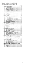
TABLE OF CONTENTS
PAGE
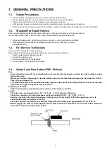
1 GENERAL PRECAUTIONS
-------------------------------------
1.1. Safety Precautions-----------------------------------------3
1.2. Standard for Repair Service -----------------------------3
1.3. For Service Technicians ----------------------------------3
1.4. About Lead Free Solder (PbF: Pb free) --------------3
1.5. About RoHS -------------------------------------------------4
2 SPECIFICATIONS
-------------------------------------------------
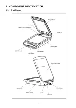
3 COMPONENT IDENTIFICATION
------------------------------
3.1. Part Names --------------------------------------------------7
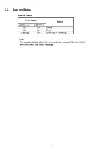
3.2. Scanner Status----------------------------------------------8
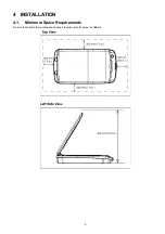
4 INSTALLATION
-----------------------------------------------------
4.1. Minimum Space Requirements -------------------------9
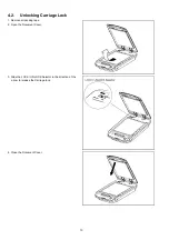
4.2. Unlocking Carriage Lock ------------------------------- 10
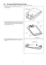
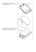
4.3. Reversing Flatbed Sheet (as required) ------------- 11
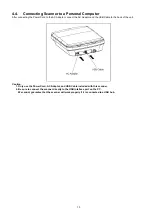
4.4. Connecting Scanner to a Personal Computer ---- 13
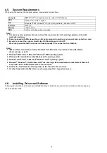
4.5. System Requirements ---------------------------------- 14
4.6. Installing Driver and Software ------------------------ 14
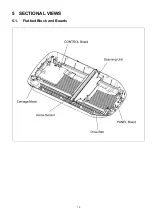
5 SECTIONAL VIEWS
---------------------------------------------
5.1. Flatbed Block and Boards ----------------------------- 15
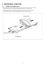
6 MECHANICAL FUNCTION
------------------------------------
6.1. Carriage Drive Mechanism ---------------------------- 16
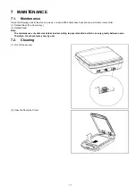
7 MAINTENANCE
--------------------------------------------------
7.1. Maintenance----------------------------------------------- 17
7.2. Cleaning ---------------------------------------------------- 17
8 DISASSEMBLY INSTRUCTIONS
----------------------------
8.1. Disassembly Flowchart --------------------------------- 19
8.2. Disassembling -------------------------------------------- 20
9 SERVICE UTILITY & SELF TEST
---------------------------
9.1. Main Menu Indication for Service Utility ------------ 29
9.2. List of Functions for Service Utility------------------- 30
9.3. Operation--------------------------------------------------- 31
10 TROUBLESHOOTING
------------------------------------------
10.1. Troubleshooting-1 (when no error message is
displayed on PC) ----------------------------------------- 35
10.2. Troubleshooting-2 (when an error message is
displayed on PC) ----------------------------------------- 37
11 CIRCUIT DESCRIPTION
---------------------------------------
11.1. Block Diagram-1 (Image Processing)--------------- 43
11.2. Block Diagram-2 (Board) ------------------------------- 44
11.3. Explanation of Connector ------------------------------ 45
12 PARTS LOCATION AND MECHANICAL PARTS
LIST
------------------------------------------------------------------
12.1. Main Body-------------------------------------------------- 48
12.2. Packing ----------------------------------------------------- 50
Summary of Contents for KV-SS080
Page 7: ...7 3 COMPONENT IDENTIFICATION 3 1 Part Names ...
Page 8: ...8 3 2 Scanner Status ...
Page 15: ...15 5 SECTIONAL VIEWS 5 1 Flatbed Block and Boards ...
Page 44: ...44 11 2 Block Diagram 2 Board ...
Page 47: ...47 12 PARTS LOCATION AND MECHANICAL PARTS LIST ...
Page 48: ...48 12 1 Main Body ...
Page 50: ...50 12 2 Packing ...


