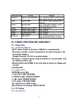
Items
Adjustment
Point
Procedure*
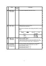
Check
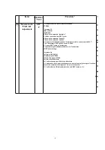
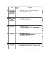
(D)
Charge Control
Check & Charge
Current Monitor
Confirmation
-
1. Apply 6V between TP5(+) and TP6(-) with current limit of PSU to 200mA.
2. Confirm that the charge current is ON/OFF.
3. SW to decrease current limit of PSU to 100mA.
4. Confirm that the charge current is stable.
IC1,D4,L4,
L5,Q2,Q3,
R6,D2,R22,
C26,F1,R21,
(E)
*
Charge Detection
(OFF)
Confirmation
-
1. Stop supplying 6V to TP5(+) and TP6(-).
2. Execute the command "charge".
3. Confirm that the returned value is 0x00 (hex).
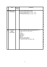
IC1,D4,L4,
L5,Q2,Q3,
R6,D2,R22,
C26,F1,R21,
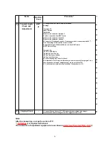
(F)
*
Battery Monitor
Confirmation
-
1. Apply 2.3V ± 0.005V between TP3(+) and TP4(-).
2. Execute the command "readbatt".
3. Subtract "0x06" from returned value which define "XX" and confirm that the "XX" is
0x92 ~ 0xA2 (hex).
4. Execute the command "WRTBAT2 XX".
IC1,D4,L4,
L5,Q2,Q3,
R6,D2,R22,
C26,F1,R21,
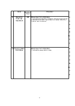
(G)
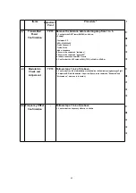
Battery low
Confirmation
-
1. Apply 2.40V between TP3(+) and TP4(-).
2. Confirm that there is no Speaker sound (Battery low alarm).
3. Apply 2.20V between TP3(+) and TP4(-).
4. Confirm that there is Speaker sound (Battery low alarm).
IC1,F1,R21,
R4,C33,C12,
C31,R17,R20,
C10,C11,D6,
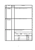
(H)
*
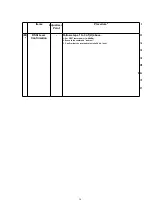
BBIC Clock
Adjusment
TP19
1. Execute the command "conttx".
2. Adjust the frequency of TP19 executing thecommand "setfreq 00 xx (where xx is the
value)" so that the reading of the frequency counter is 10.368000MHz ± 0.000003Hz.
IC1,L3,C57,
IC3,X1,C16,
41
Summary of Contents for KX-A140EXC
Page 46: ...18 FREQUENCY TABLE MHz 46 ...
Page 52: ...24 CPU DATA BASE UNIT 24 1 IC2 BBIC 52 ...
Page 56: ...45 MICP A I 56 ...
Page 60: ...60 ...
Page 61: ...28 CABINET AND ELECTRICAL PARTS LOCATION HANDSET 29 ACCESSORIES AND PACKING MATERIALS 61 ...
Page 62: ...30 TERMINAL GUIDE OF THE ICs TRANSISTORS AND DIODES 30 1 Base Unit 30 2 Handset 62 ...
Page 91: ...4 1 5 8 PbF 1 28 18 IC3 IC2 IC1 11 64 1 16 17 32 49 48 33 Marked ...
Page 93: ...Marked PbF IC1 IC2 100 80 5 8 4 1 50 51 30 31 1 11 18 1 28 IC3 ...

