KX-TCD400RUB
I
KX-TCD400RUC
I
KX-TCD400RUF
I
KX-A140RUB
I
KX-A140RUC
I
KX-A140RUF
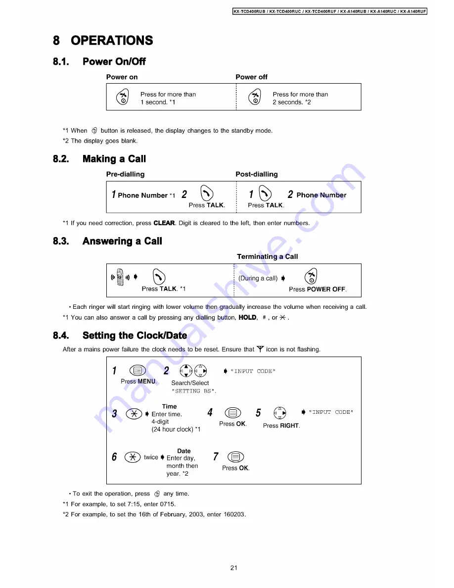
8 OPERATIONS
8.1.
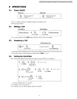
Power On/Off
P o w e r o n
P o w e r o ff
( £)
Press for more than
!
( £)
Press for more than
1 second. *1
2 seconds. *2
*1 When (f) button is released, the display changes to the standby mode.
*2 The display goes blank.
8.2.
Making a Call
P re -d ia llin g
P o s t- d ia llin g
1
P h o n e N u m b e r *1
2
&
j
»
2
P h o n e N u m b e r
Press TALK.
Press TALK.
*1 If you need correction, press CLEAR. Digit is cleared to the left, then enter numbers.
8.3.
Answering a Call
•
Each ringer will start ringing with lower volume then gradually increase the volume when receiving a call.
*1 You can also answer a call by pressing any dialling button, HOLD, # , or -X-.
8.4.
Setting the Clock/Date
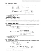
After a mains power failure the clock needs to be reset. Ensure that ^ icon is not flashing.
• To exit the operation, press
<$
any time.
*1 For example, to set 7:15, enter 0715.
*2 For example, to set the 16th of February, 2003, enter 160203.
21
Summary of Contents for KX-A140RUB
Page 48: ...817 19 BLOCK DIAGRAM BASE UNIT KX TCD400RUB RUC RUF BLOCK DIAGRAM BASE UNIT ...
Page 67: ...KX TCD400RUB I KX TCD400RUC I KX TCD400RUF I KX A140RUB I KX A140RUC I KX A140RUF 67 ...
Page 72: ...33 5 Memo kX TCD400RUB KX TCD400RUC KX TGD400RUF KX A140RUB KX A140RUC KX A140RUF 72 ...
Page 76: ... kX TCD400RUB I KX TCD400RUC KX TCD400RUF KX A140RUB KX A140RUC KX A140RUF 76 ...
Page 80: ...08 37 2 Flow Solder Side View KX A140RUB RUC RUF CIRCUIT BOARD HANDSET Flow Solder Side View ...

