KX-TCD400RUB / KX-TCD400RUC / KX-TCD400RUF / KX-A140RUB / KX-A140RUC / KX-A140RUF
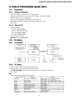
12 CHECK PROCEDURE (BASE UNIT)
12.1. Preparation
12.1.1. Equipment Required
• DECT tester: Rohde & Schwarz, CMD 60 is recommended.
• Frequency counter: it must be precise to be able to measure 1Hz (precision; ±4ppm).
Hewlett Packard, 53131A is recommended.
• DC power: it must be able to output at least 1A current under 9V.
• Digital multi-meter (DMM): it must be able to measure voltage and current.
• Oscilloscope
12.1.2. JIGs and PC
• EEPROM serial JIGs
1. I2C PCB: PQZZTCD705BX
2. RS232C cable: PQZZ1CD705BX
3. Clip cable: PQZZ2CD705BX
4. DC cable: PQZZ3CD705BX
• PC which runs in DOS mode
• Batch file for setting: PQZZTCD410E
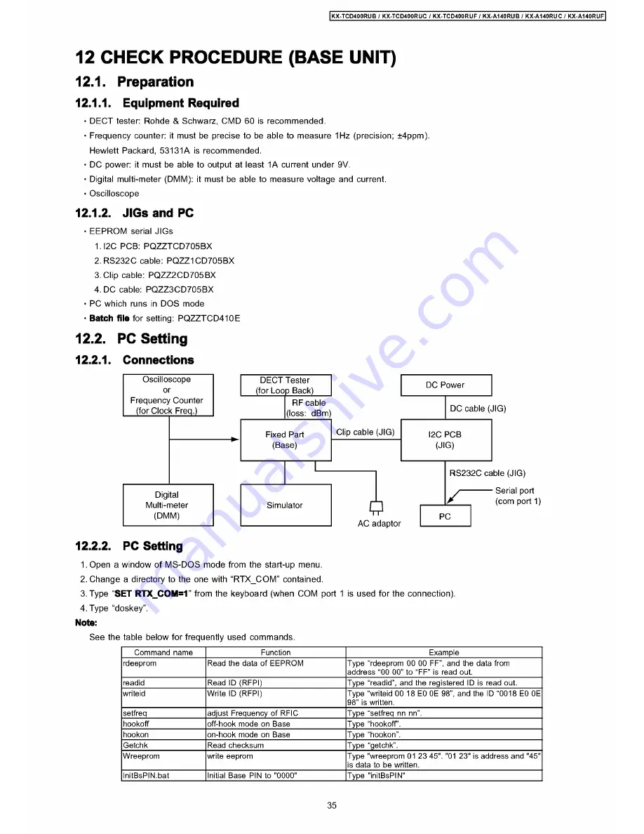
12.2.
12.2.1.
PC Setting
Connections
Oscilloscope
or
Frequency Counter
(for Clock Freq.)
Digital
Multi-meter
(DMM)
DECT Tester
DC Power
(for Loop Back)
RF cable
(loss: dBm)
DC cable (JIG)
Fixed Part
Clip cable (JIG)
I2C PCB
(Base)
(JIG)
Simulator
0
AC adaptor
RS232C cable (JIG)
/
PC
Serial port
(com port 1)
12.2.2. PC Setting
1. Open a window of MS-DOS mode from the start-up menu.
2. Change a directory to the one with “RTX_COM” contained.
3. Type “SET RTX_COM=1” from the keyboard (when COM port 1 is used for the connection).
4. Type “doskey”.
Note:
See the table below for frequently used commands.
Command name
Function
Example
rdeeprom
Read the data of EEPROM
Type “rdeeprom 00 00 FF”, and the data from
address “00 00” to “ FF” is read out.
readid
Read ID (RFPI)
Type “readid”, and the registered ID is read out.
writeid
Write ID (RFPI)
Type “writeid 00 18 E0 0E 98” , and the ID “0018 E0 0E
98” is written.
setfreq
adjust Frequency of RFIC
Type “setfreq nn nn” .
hookoff
off-hook mode on Base
Type “hookoff.
hookon
on-hook mode on Base
Type “hookon”.
Getchk
Read checksum
Type “getchk”.
Wreeprom
write eeprom
Type "wreeprom 01 23 45". "01 23" is address and "45"
is data to be written.
InitBsPIN.bat
Initial Base PIN to "0000"
Type "initBsPIN"
35
Summary of Contents for KX-A140RUB
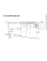
Page 48: ...817 19 BLOCK DIAGRAM BASE UNIT KX TCD400RUB RUC RUF BLOCK DIAGRAM BASE UNIT ...
Page 67: ...KX TCD400RUB I KX TCD400RUC I KX TCD400RUF I KX A140RUB I KX A140RUC I KX A140RUF 67 ...
Page 72: ...33 5 Memo kX TCD400RUB KX TCD400RUC KX TGD400RUF KX A140RUB KX A140RUC KX A140RUF 72 ...
Page 76: ... kX TCD400RUB I KX TCD400RUC KX TCD400RUF KX A140RUB KX A140RUC KX A140RUF 76 ...
Page 80: ...08 37 2 Flow Solder Side View KX A140RUB RUC RUF CIRCUIT BOARD HANDSET Flow Solder Side View ...

