KX-TCD400RUB
I
KX-TCD400RUC
I
KX-TCD400RUF
I
KX-A140RUB
I
KX-A140RUC
I
KX-A140RUF
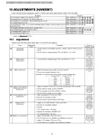
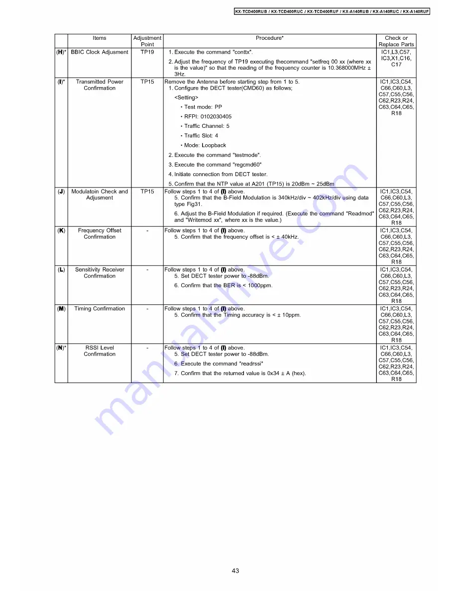
Items
Adjustment
Point
Procedure*
Check or
Replace Parts
(
H
)*
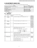
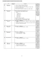
BBIC Clock Adjusment
TP19
1. Execute the command "conttx".
2. Adjust the frequency of TP19 executing thecommand "setfreq 00 xx (where xx
is the value)" so that the reading of the frequency counter is 10.368000MHz ±
3Hz.
7,
6,
q
o
^
2
.X
O
IC1
IC3
(
I
)*
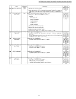
Transmitted Power
Confirmation
TP15
Remove the Antenna before starting step from 1 to 5.
1. Configure the DECT tester(CMD60) as follows;
<Setting>
• Test mode: PP
• RFPI: 0102030405
• Traffic Channel:
5
• Traffic Slot: 4
• Mode: -oopback
2. Execute the command "testmode".
3. Execute the command "regcmd60"
4. Initiate connection from DECT tester.
5. Confirm that the NTP value at A201 (TP15) is 20dBm ~ 25dBm
IC1,IC3,C54,
о66,о60,-3,
C57,C55,C56,
C62,R23,R24,
C63,C64,C65,
R18
(
J
)
Modulatoin Check and
Adjusment
TP15
Follow steps 1 to 4 of
(I)
above.
5. Confirm that the B-Field Modulation is 340kHz/div ~ 402kHz/div using data
type Fig31.
6. Adjust the B-Field Modulation if required. (Execute the command "Readmod"
and "Writemod xx", where xx is the value.)
IC1,IC3,C54,
о66,о60,-3,
C57,C55,C56,
C62,R23,R24,
C63,C64,C65,
R18
(
K
)
Frequency Offset
Confirmation
Follow steps 1 to 4 of
(I)
above.
5. Confirm that the frequency offset is < ± 40kHz.
I01,I03,054,
о66,о60,-3,
о57,о55,о56,
C62,R23,R24,
о63,о64,о65,
R18
(
L
)
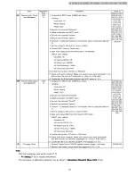
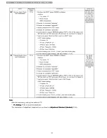
Sensitivity Receiver
Confirmation
Follow steps 1 to 4 of
(I)
above.
5. Set DECT tester power to -88dBm.
6. Confirm that the BER is < 1000ppm.
IC1,IC3,C54,
о66,о60,-3,
о57,о55,о56,
C62,R23,R24,
о63,о64,о65,
R18
(
M
)
Timing Confirmation
Follow steps 1 to 4 of
(I)
above.
5. Confirm that the Timing accuracy is < ± 10ppm.
I01,I03,054,
о66,о60,-3,
о57,о55,о56,
C62,R23,R24,
C63,C64,C65,
R18
(
N
)*
RSSI -evel
Confirmation
Follow steps 1 to 4 of
(I)
above.
5. Set DECT tester power to -88dBm.
6. Execute the command "readrssi"
7. Confirm that the returned value is 0x34 ± A (hex).
I01,I03,054,
о66,о60,-3,
о57,о55,о56,
C62,R23,R24,
о63,о64,о65,
R18
43
Summary of Contents for KX-A140RUB
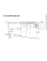
Page 48: ...817 19 BLOCK DIAGRAM BASE UNIT KX TCD400RUB RUC RUF BLOCK DIAGRAM BASE UNIT ...
Page 67: ...KX TCD400RUB I KX TCD400RUC I KX TCD400RUF I KX A140RUB I KX A140RUC I KX A140RUF 67 ...
Page 72: ...33 5 Memo kX TCD400RUB KX TCD400RUC KX TGD400RUF KX A140RUB KX A140RUC KX A140RUF 72 ...
Page 76: ... kX TCD400RUB I KX TCD400RUC KX TCD400RUF KX A140RUB KX A140RUC KX A140RUF 76 ...
Page 80: ...08 37 2 Flow Solder Side View KX A140RUB RUC RUF CIRCUIT BOARD HANDSET Flow Solder Side View ...


