KX-TCD400RUB
I
KX-TCD400RUC
I
KX-TCD400RUF
I
KX-A140RUB
I
KX-A140RUC
I
KX-A140RUF
6 SETTINGS
6.1.
Connection
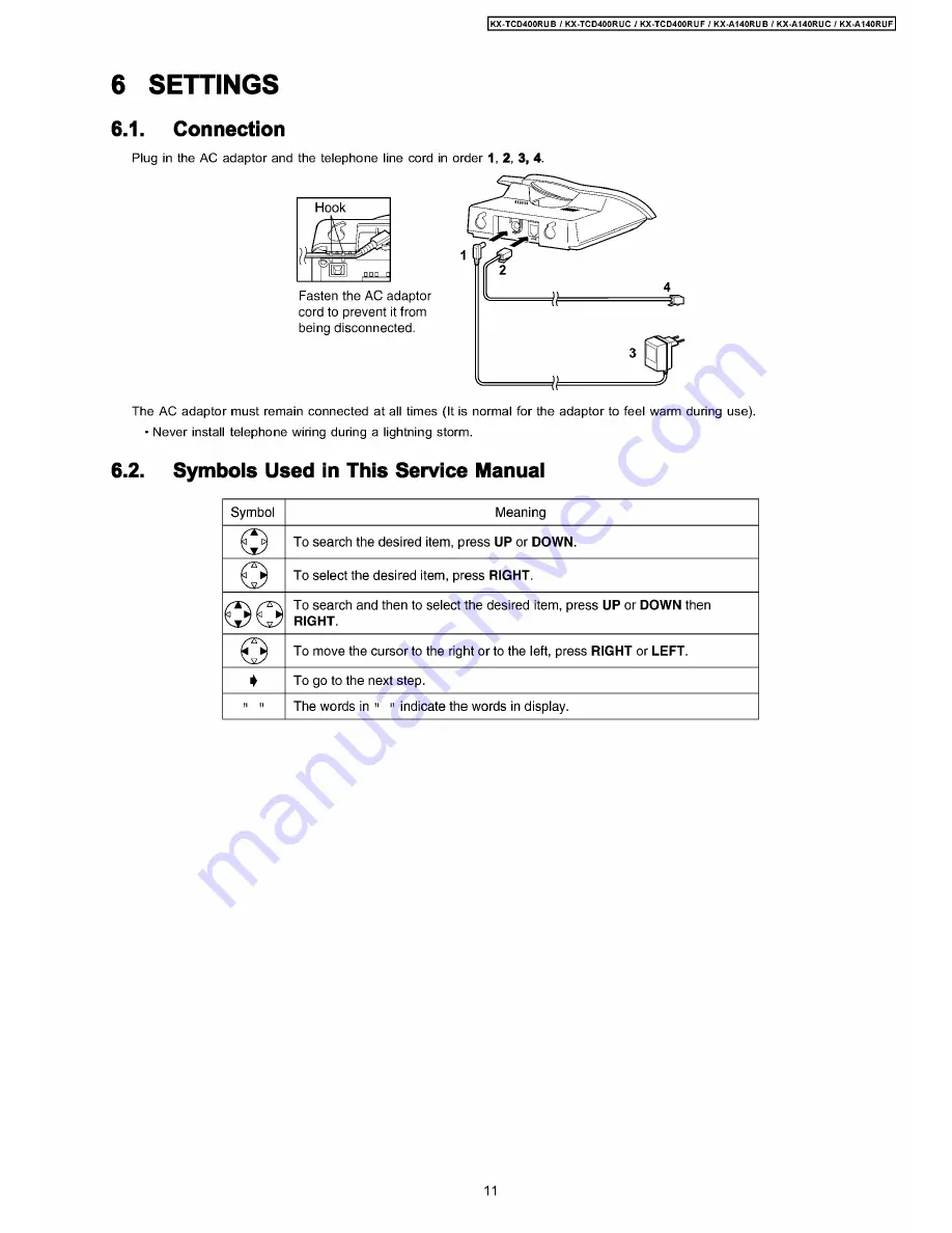
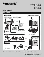
Plug in the AC adaptor and the telephone line cord in order 1, 2, 3, 4.
Fasten the AC adaptor
cord to prevent it from
being disconnected.
The AC adaptor must remain connected at all times (It is normal for the adaptor to feel warm during use).
• Never install telephone wiring during a lightning storm.
6.2.
Symbols Used in This Service Manual
Symbol
Meaning
©
To search the desired item, press UP or DOWN.
G
To select the desired item, press RIGHT.
OO
To search and then to select the desired item, press UP or DOWN then
RIGHT.
©
To move the cursor to the right or to the left, press RIGHT or LEFT.
♦
To go to the next step.
ii П
The words in " " indicate the words in display.
11
Summary of Contents for KX-A140RUC
Page 48: ...817 19 BLOCK DIAGRAM BASE UNIT KX TCD400RUB RUC RUF BLOCK DIAGRAM BASE UNIT ...
Page 67: ...KX TCD400RUB I KX TCD400RUC I KX TCD400RUF I KX A140RUB I KX A140RUC I KX A140RUF 67 ...
Page 72: ...33 5 Memo kX TCD400RUB KX TCD400RUC KX TGD400RUF KX A140RUB KX A140RUC KX A140RUF 72 ...
Page 76: ... kX TCD400RUB I KX TCD400RUC KX TCD400RUF KX A140RUB KX A140RUC KX A140RUF 76 ...
Page 80: ...08 37 2 Flow Solder Side View KX A140RUB RUC RUF CIRCUIT BOARD HANDSET Flow Solder Side View ...


