KX-TCD400RUB
I
KX-TCD400RUC
I
KX-TCD400RUF
I
KX-A140RUB
I
KX-A140RUC
I
KX-A140RUF
15 ADJUSTMENTS (HANDSET)
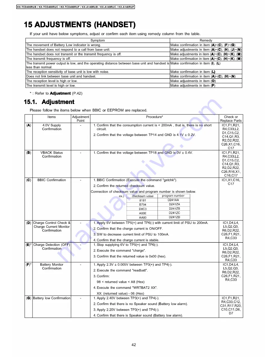
If your unit have below symptoms, adjust or confirm each item using remedy column from the table.
Symptom
Remedy
The movement of Battery Low indicator is wrong.
Make confirmation in item (
A
)~(
C
), (
F
)~(
G
)
The handset does not respond to a call from base unit.
Make adjustments in item (
A
)~(
C
), (
H
), (
J
)~(
N
)
The handset does not transmit or the transmit frequency is off.
Make adjustments in item (
A
)~(
C
), (
H
)~(
K
), (
M
)
The transmit frequency is off.
Make confirmation in item (
A
)~(
C
), (
H
)~(
K
), (
M
)
The transmit power output is low, and the operating distance between base unit and handset is
less than normal.
Make confirmation in item (
I
), (
L
)
The reception sensitivity of base unit is low with noise.
Make confirmation in item (
L)
Does not link between base unit and handset.
Make confirmation in item (
A
)~(
C
), (
H
)~(
N
)
The reception level is high or low.
Make adjustments in item (
O
)
The transmit level is high or low.
Make adjustments in item (
P
)
* : Refer to
Adjustment
(P.42)
15.1. Adjustment
Please follow the items below when BBIC or EEPROM are replaced.
Items
Adjustment
Point
Procedure*
Check or
Replace Parts
(A)
4.0V Supply
Confirmation
1. Confirm that the consumption current is < 200mA , that is, there is no short
circuit.
2. Confirm that the voltage between TP14 and GND is 4.1V ± 0.2V.
IC1,F1,R21,
R4,C33,L2,
D1,C15,C2,
C14,Q1,R3,
R2,D2,R22,
C26,X1,C16,
C17
(B)
VBACK Status
Confirmation
1. Confirm that the voltage between TP18 and GND is 0V ± 0.4V.
IC1,F1,R21,
R4,C33,L2,
D1,C15,C2,
C14,Q1,R3,
R2,D2,R22,
C26,R16,X1,
C16,C17
(C)
BBIC Confirmation
1. BBIC Confirmation (Execute the command "getchk").
2. Confirm the returned checksum value.
Connection of checksum value and program number is shown below.
checksum value
program number
8181
D241AA
B794
D241ZA
D8C3
D241ZB
A00E
D241ZC
AA80
D241ZD
IC1,X1,C16,
C17
(D)
Charge Control Check &
Charge Current Monitor
Confirmation
1. Apply 6V between TP5(+) and TP6(-) with current limit of PSU to 200mA.
2. Confirm that the charge current is ON/OFF.
3. SW to decrease current limit of PSU to 100mA.
4. Confirm that the charge current is stable.
IC1,D4,L4,
L5,Q2,Q3,
R6,D2,R22,
C26,F1,R21,
R4,C33
(E)*
Charge Detection (OFF)
Confirmation
1. Stop supplying 6V to TP5(+) and TP6(-).
2. Execute the command "charge".
3. Confirm that the returned value is 0x00 (hex).
IC1,D4,L4,
L5,Q2,Q3,
R6,D2,R22,
C26,F1,R21,
R4,C33
(F)*
Battery Monitor
Confirmation
1. Apply 2.3V ± 0.005V between TP3(+) and TP4(-).
2. Execute the command "readbatt".
3. Confirm:
98 < returned value < A8 (Hex)
4. Execute the command "WRTBAT2 XX".
XX: (returned value) - 06 (Hex)________________
IC1,D4,L4,
L5,Q2,Q3,
R6,D2,R22,
C26,F1,R21,
R4,C33
(G)
Battery low Confirmation
1. Apply 2.40V between TP3(+) and TP4(-).
2. Confirm that there is no Speaker sound (Battery low alarm).
3. Apply 2.20V between TP3(+) and TP4(-).
4. Confirm that there is Speaker sound (Battery low alarm).
IC1,F1,R21,
R4,C33,C12,
C31,R17,R20,
C10,C11,D6,
D7
42
Summary of Contents for KX-A140RUC
Page 48: ...817 19 BLOCK DIAGRAM BASE UNIT KX TCD400RUB RUC RUF BLOCK DIAGRAM BASE UNIT ...
Page 67: ...KX TCD400RUB I KX TCD400RUC I KX TCD400RUF I KX A140RUB I KX A140RUC I KX A140RUF 67 ...
Page 72: ...33 5 Memo kX TCD400RUB KX TCD400RUC KX TGD400RUF KX A140RUB KX A140RUC KX A140RUF 72 ...
Page 76: ... kX TCD400RUB I KX TCD400RUC KX TCD400RUF KX A140RUB KX A140RUC KX A140RUF 76 ...
Page 80: ...08 37 2 Flow Solder Side View KX A140RUB RUC RUF CIRCUIT BOARD HANDSET Flow Solder Side View ...


