KX-TCD400RUB
I
KX-TCD400RUC
I
KX-TCD400RUF
I
KX-A140RUB
I
KX-A140RUC
I
KX-A140RUF
27 EEPROM LAYOUT (HANDSET)
27.1. Scope
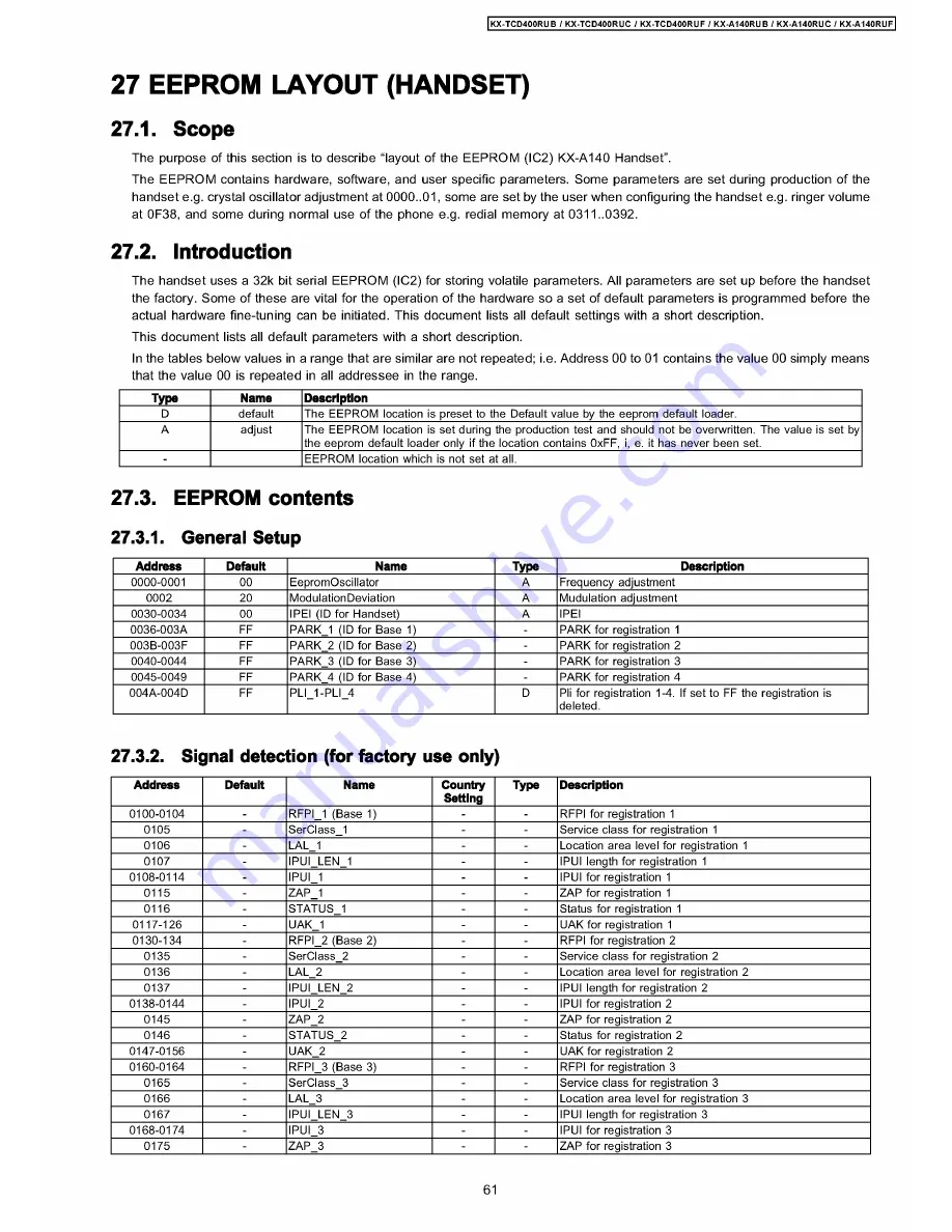
The purpose of this section is to describe “layout of the EEPROM (IC2) KX-A140 Handset”.
The EEPROM contains hardware, software, and user specific parameters. Some parameters are set during production of the
handset e.g. crystal oscillator adjustment at 0000..01, some are set by the user when configuring the handset e.g. ringer volume
at 0F38, and some during normal use of the phone e.g. redial memory at 0311..0392.
27.2. Introduction
The handset uses a 32k bit serial EEPROM (IC2) for storing volatile parameters. All parameters are set up before the handset
the factory. Some of these are vital for the operation of the hardware so a set of default parameters is programmed before the
actual hardware fine-tuning can be initiated. This document lists all default settings with a short description.
This document lists all default parameters with a short description.
In the tables below values in a range that are similar are not repeated; i.e. Address 00 to 01 contains the value 00 simply means
that the value 00 is repeated in all addressee in the range.
Type
Name
Description
D
default
The EEPROM location is preset to the Default value by the eeprom default loader.
A
adjust
The EEPROM location is set during the production test and should not be overwritten. The value is set by
the eeprom default loader only if the location contains 0xFF, i, e. it has never been set.
-
EEPROM location which is not set at all.
27.3. EEPROM contents
27.3.1. General Setup
Address
Default
Name
Type
Description
0000-0001
00
EepromOscillator
A
Frequency adjustment
0002
20
ModulationDeviation
A
Mudulation adjustment
0030-0034
00
IPEI (ID for Handset)
A
IPEI
0036-003A
FF
PARK_1 (ID for Base 1)
-
PARK for registration 1
003B-003F
FF
PARK_2 (ID for Base 2)
-
PARK for registration 2
0040-0044
FF
PARK_3 (ID for Base 3)
-
PARK for registration 3
0045-0049
FF
PARK_4 (ID for Base 4)
-
PARK for registration 4
004A-004D
FF
PLI_1-PLI_4
D
Pli for registration 1-4. If set to FF the registration is
deleted.
27.3.2. Signal detection (for factory use only)
Address
Default
Name
Country
Setting
Type
Description
0100-0104
-
RFPI_1 (Base 1)
-
-
RFPI for registration 1
0105
-
SerClass 1
-
-
Service class for registration 1
0106
-
LAL 1
-
-
Location area level for registration 1
0107
-
IPUI LEN 1
-
-
IPUI length for registration 1
0108-0114
-
IPUI 1
-
-
IPUI for registration 1
0115
-
ZAP 1
-
-
ZAP for registration 1
0116
-
STATUS 1
-
-
Status for registration 1
0117-126
-
UAK 1
-
-
UAK for registration 1
0130-134
-
RFPI_2 (Base 2)
-
-
RFPI for registration 2
0135
-
SerClass 2
-
-
Service class for registration 2
0136
-
LAL 2
-
-
Location area level for registration 2
0137
-
IPUI LEN 2
-
-
IPUI length for registration 2
0138-0144
-
IPUI 2
-
-
IPUI for registration 2
0145
-
ZAP 2
-
-
ZAP for registration 2
0146
-
STATUS 2
-
-
Status for registration 2
0147-0156
-
UAK 2
-
-
UAK for registration 2
0160-0164
-
RFPI_3 (Base 3)
-
-
RFPI for registration 3
0165
-
SerClass 3
-
-
Service class for registration 3
0166
-
LAL 3
-
-
Location area level for registration 3
0167
-
IPUI LEN 3
-
-
IPUI length for registration 3
0168-0174
-
IPUI 3
-
-
IPUI for registration 3
0175
-
ZAP_3
-
-
ZAP for registration 3
61
Summary of Contents for KX-A140RUC
Page 48: ...817 19 BLOCK DIAGRAM BASE UNIT KX TCD400RUB RUC RUF BLOCK DIAGRAM BASE UNIT ...
Page 67: ...KX TCD400RUB I KX TCD400RUC I KX TCD400RUF I KX A140RUB I KX A140RUC I KX A140RUF 67 ...
Page 72: ...33 5 Memo kX TCD400RUB KX TCD400RUC KX TGD400RUF KX A140RUB KX A140RUC KX A140RUF 72 ...
Page 76: ... kX TCD400RUB I KX TCD400RUC KX TCD400RUF KX A140RUB KX A140RUC KX A140RUF 76 ...
Page 80: ...08 37 2 Flow Solder Side View KX A140RUB RUC RUF CIRCUIT BOARD HANDSET Flow Solder Side View ...


