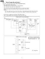
Using a different winding ratio results in the voltage function given by the formula in figure (c).
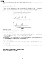
As you can see, it is possible to keep VO constant by changing the ratio of TON and TOFF in response to variations in input
voltage.
Response to Variations in Output Current
In this case, VO is kept constant by controlling only TON without changing the ratio between TON and TOFF in response to
variations in output current. Figure B (a) and (b) shows how TON varies in response to variations in output current.
The input current must be increased as output current increases, making TON longer. The value obtained by dividing the surface
area of the sawtooth waves in this figure by the time interval gives the average input current.
<Figure B>
[Surge Absorber Circuit]
This circuit is for absorbing surge voltage generated by the transformer.
[Control Circuit and Detecting Circuit]
The control circuit amplifies the output with increased voltage detected in the error detecting circuit. Then it drives the main
transistor.
In this power supply, the duty ratio is defined by changing the ON period of the main transistor.
This is shown as follows.
When the output voltage of the 24V circuit increases, the current of the photo coupler PC101 increases, the pulse width of the
output control IC becomes narrower and the ON period of Q101 becomes shorter.
[Over Current Limiter (O.C.L)]
The highest Ton (while Q101 is ON) is limited by a limiter circuit (control Circuit) of 24V. The 24V output is limited by this circuit.
[Over Voltage Circuit]
If the 24V output increases because the error detecting circuit or control circuit is broken, D204 will short causing the 24V output
to go to 0 V.
Dummy load method (to quickly check the power supply output)
Refer to 2.3.4.5. Power Supply Board Section.
20
KX-F206TW
Summary of Contents for KX-F206TW
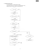
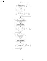
Page 9: ...2 Troubleshooting Flow Chart 9 KX F206TW ...
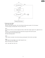
Page 10: ...10 KX F206TW ...

