|
63
|
TROUBLESHOOTING GUIDE
KX-F680BX/KX-F2681BX
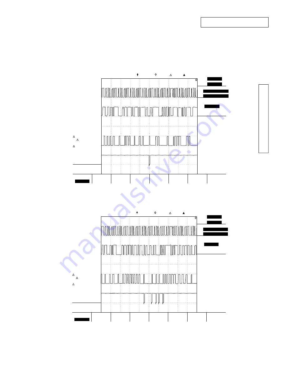
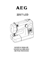
Please observe A0, D0, ROMCE, MDMCS.
Below graph show you the wave form that is observed when unit (board) is working correctly. Both graph are good wave.
CH1 5V/div
CH2 5V/div
CH3 5V/div
CH4 5V/div
W1 5
µ
s/div
Length 1k
W2 5
µ
s/div
Length 1k
Sampling
Normal
20Msps
Marker 1
T 2098.80
µ
s
V 5.0 V
Marker 2
T 7.50
µ
s
V 0.4 V
T -2091.30
µ
s
1/ T
478.2 Hz
V -4.6 V
W1
5µs
W2
5µs
Position
W1
2083.20µs
W2
25.10µs
Time
Time Base
Roll
Off
Time Base
External
Internal
Internal
-40.0V
2083.20
µ
s
2133.20
µ
s
Time/div
10.0V
H1 W1
A0
D0
ROMCS
MDMCS
OK
Trigger CH1/2 MEM1 MEM2
CH1 5V/div
CH2 5V/div
CH3 5V/div
CH4 5V/div
W1 5
µ
s/div
Length 1k
W2 5
µ
s/div
Length 1k
Sampling
Normal
20Msps
Marker 1
T 2376.70
µ
s
V 0.4 V
Marker 2
T 7.50
µ
s
V 5.0 V
T -2369.20
µ
s
1/ T
422.1 Hz
V 4.6 V
W1
5µs
W2
5µs
Position
W1
2384.60µs
W2
25.10µs
Time
Time Base
Roll
Off
Time Base
External
Internal
Internal
-40.0V
2384.60
µ
s
2434.60
µ
s
Time/div
10.0V
H1 W1
A0
D0
ROMCS
MDMCS
OK
Trigger CH1/2 MEM1 MEM2
Summary of Contents for KX-F680BX
Page 1: ......
Page 11: ......
Page 106: ......
Page 107: ......
Page 108: ......
Page 109: ......
Page 110: ......
Page 111: ......
Page 112: ......
Page 113: ......
Page 114: ......
Page 115: ......
Page 116: ......
Page 117: ......
Page 118: ......
Page 119: ......
Page 120: ......
Page 121: ......
Page 122: ......
Page 123: ......
Page 124: ......
Page 125: ......
Page 126: ......
Page 127: ......
Page 128: ......
Page 129: ......
Page 130: ... 165 KX F680BX KX F2681BX EC1 EC2 EC3 EC4 EC5 EC6 EC7 EC9 EC10 EC11 EC12 EC13 EC8 TOOLS ...
Page 131: ......
Page 133: ......
Page 134: ......
Page 135: ......
Page 136: ......


