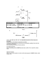
No.
Symptom
Content
Possible cause
1
The paper is not fed properly when faxing.
(Nor in the copy mode.)
Troubleshooting
Problem with the
feeding mechanism.
2
The fax usually transmits successfully but
sometimes fails. (The unit can copy
documents.)
Troubleshooting
Problem with the service
line or with the
receiver's fax.
3
The fax usually receives successfully but
sometimes fails.
(The unit can copy documents.)
Troubleshooting
Problem with the service
line or with the
transmitter's fax.
4
The fax completely fails to transmit or
receive.
(The unit can copy documents.)
Troubleshooting
Problem with the
electric circuit.
5
The fax fails either to transmit or receive
when making a long distance or an
international call.
(The unit can copy documents.)
Detailed description
of the possible
causes (Similar to
troubleshooting
items No.2 and No.3.)
Problem with the service
line.
6
The fax image is poor when transmitting or
receiving during a long distance or an
international call.
7
No.1-No.5
The troubleshooting
procedure for each
error code will be
printed on the
communication
result report.
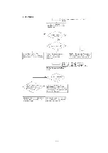
6.6.5.1. DEFECTIVE FACSIMILE SECTION
6.6.5.1.1. TRANSMIT PROBLEM
103
Summary of Contents for KX-FHD332C
Page 33: ...3 Open the back cover 4 Remove the jammed recording paper 33 ...
Page 46: ...5 1 DISASSEMBLY FLOW CHART 5 1 1 UPPER CABINET SECTION 46 ...
Page 49: ...5 2 2 HOW TO REMOVE THE OPERATION PANEL BLOCK 49 ...
Page 50: ...5 2 3 HOW TO REMOVE THE OPERATION BOARD AND LCD 50 ...
Page 51: ...5 2 4 HOW TO REMOVE THE IMAGE SENSOR CIS 51 ...
Page 52: ...5 2 5 HOW TO REMOVE THE THERMAL HEAD 52 ...
Page 53: ...5 2 6 HOW TO REMOVE THE PLATEN ROLLER AND BACK COVER 53 ...
Page 54: ...5 2 7 HOW TO REMOVE THE PICKUP ROLLER 54 ...
Page 55: ...5 2 8 HOW TO REMOVE THE CASSETTE LEVER 55 ...
Page 56: ...5 2 9 HOW TO REMOVE THE BOTTOM FRAME 56 ...
Page 57: ...5 2 10 HOW TO REMOVE THE DIGITAL ANALOG POWER SUPPLY SENSOR BOARDS AND AC INLET 57 ...
Page 58: ...5 2 11 HOW TO REMOVE THE MOTOR BLOCK AND SEPARATION ROLLER 58 ...
Page 59: ...5 2 12 HOW TO REMOVE THE GEARS OF MOTOR BLOCK 59 ...
Page 60: ...5 3 INSTALLATION POSITION OF THE LEAD WIRES 60 ...
Page 74: ...2 Left margin Top margin 3 Thermal head 1 dot 74 ...
Page 77: ...CROSS REFERENCE PROGRAM MODE TABLE 6 4 2 PROGRAM MODE TABLE 77 ...
Page 81: ...Note The above values are the default values 6 5 3 HISTORY 81 ...
Page 90: ...Fig B 90 ...
Page 98: ...6 6 4 12 A BLANK PAGE IS RECEIVED 98 ...
Page 116: ...116 ...
Page 117: ...CROSS REFERENCE TEST FUNCTIONS 117 ...
Page 118: ...CROSS REFERENCE TEST FUNCTIONS 118 ...
Page 119: ...CROSS REFERENCE TEST FUNCTIONS 119 ...
Page 120: ...CROSS REFERENCE TEST FUNCTIONS 120 ...
Page 121: ...121 ...
Page 122: ...122 ...
Page 123: ...123 ...
Page 128: ...128 ...
Page 133: ...I O and Pin No Diagram 6 6 7 1 CHECK THE STATUS OF THE DIGITAL BOARD 133 ...
Page 139: ...3 No ring tone or No bell CROSS REFERENCE CHECK SHEET 139 ...
Page 142: ...6 6 9 2 TROUBLESHOOTING FLOW CHART 142 ...
Page 143: ...143 ...
Page 144: ...144 ...
Page 148: ...CROSS REFERENCE TEST FUNCTIONS 6 6 13 THERMAL HEAD SECTION Refer to THERMAL HEAD 148 ...
Page 149: ...7 CIRCUIT OPERATIONS 7 1 CONNECTION DIAGRAM 149 ...
Page 152: ...7 3 CONTROL SECTION 7 3 1 BLOCK DIAGRAM 7 3 2 MEMORY MAP 152 ...
Page 153: ...7 3 3 ASIC IC501 This custom IC is used for the general FAX operations 153 ...
Page 155: ...155 ...
Page 188: ...7 10 ITS Integrated Telephone System AND MONITOR SECTION 7 10 1 GENERAL 188 ...
Page 200: ...8 3 1 ITU T No 1 TEST CHART 8 3 2 ITU T No 2 TEST CHART 200 ...
Page 201: ...9 FIXTURES AND TOOLS 201 ...
Page 202: ...10 CABINET MECHANICAL AND ELECTRICAL PARTS LOCATION 10 1 GENERAL SECTION 202 ...
Page 203: ...10 2 OPERATION PANEL SECTION 203 ...
Page 204: ...10 3 BACK COVER SECTION 204 ...
Page 205: ...205 ...
Page 206: ...10 4 UPPER CABINET SECTION 206 ...
Page 207: ...10 5 LOWER CABINET P C BOARD SECTION 207 ...
Page 208: ...CROSS REFERENCE MOTOR SECTION 10 6 MOTOR SECTION 208 ...
Page 209: ...10 7 ACTUAL SIZE OF SCREWS 11 ACCESSORIES AND PACKING MATERIALS 209 ...
Page 210: ...12 REPLACEMENT PARTS LIST Notes 1 RTL Retention Time Limited Note 210 ...
Page 231: ...SW502 SW501 CN501 CHECK PFUP1301ZA 1 3 KX FHD332C SENSOR BOARD PCB5 ...


