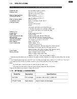
1.9. SPECIFICATIONS
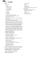
These specifications are for the U.S.A. version only. Refer to the simplified manual (cover) for other areas.
Applicable Lines:
Public Switched Telephone Network
Document Size:
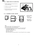
Max. 216 mm (8 1/2") in width
Max. 600 mm (23 5/8") in length
Effective Scanning Width:
208 mm (8 3/16")
Recording Paper Size:
Letter: 216×279 mm (8 1/2"×11")
Legal: 216×356 mm (8 1/2"×14")
Effective Printing Width:
208 mm (8 3/16")
Transmission Time*:
Approx. 15 sec./page (Original mode)**
Scanning Density:
Horizontal:
8 pels/mm (203 pels/inch)
Vertical:
3.85 lines/mm (98 lines/inch)—STANDARD mode
7.7 lines/mm (196 lines/inch)—FINE/HALF TONE mode
15.4 lines/mm (392 lines/inch)—SUPER FINE Mode
Halftone Level:
64-level
Scanner Type:
Contact Image Sensor (CIS)
Printer Type:
Thermal Printing
Data Compression System:
Modified Huffman (MH), Modified READ (MR)
Modem Speed:
9,600/7,200/4,800/2,400 bps; Automatic Fallback
Operating Environment:
5—35°C (41—95°F), 20—80 % RH(Relative Humidity)
Dimensions (H×W×D):
143×325×305 mm (5 5/8"×12 13/16"×12")
Mass (Weight):
Approx. 4.0 kg (8.8 lb.)
Power Consumption:
Standby: Approx. 4.0 W
Transmission: Approx. 18 W
Reception: Approx. 39 W (When receiving a 20% black document)
Copy: Approx. 48 W (When copying a 20% black document)
Maximum: Approx. 160 W (When copying a 100% black document)
Power Supply:
120 V AC, 60 Hz (This unit will not function at 50 Hz.)
Memory Capacity:
Approx. 28 pages memory reception
Approx. 25 pages memory transmission
(Based on CCITT No. 1 Test Chart in standard resolution.)
* Transmission speed depends upon the contents of the pages, resolution, telephone line conditions and capability of the receiving
unit.
** The 15 second speed is based upon the CCITT No. 1 Test Chart and original mode. (Refer to "1.11. CCITT No. 1 Test Chart".)
If the capability of the other party’s machine is inferior to your unit, the transmission time may be longer.
Note:
·
Any details given in these instructions are subject to change without notice.
·
The pictures and illustrations in these instructions may vary slightly from the actual product.
Design and specifications are subject to change without notice.
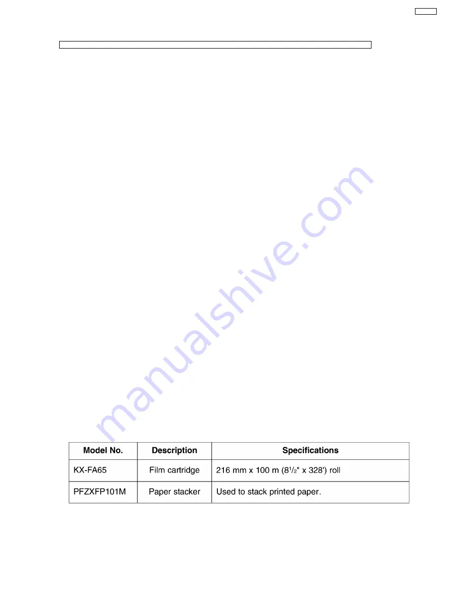
1.10. OPTIONAL ACCESSORIES
7
KX-FP101
Summary of Contents for KX-FP105BX
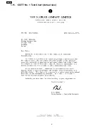
Page 36: ...1 11 CCITT No 1 Test Chart Actual size 8 KX FP101 ...
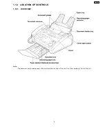
Page 38: ...1 12 2 CONTROL PANEL 10 KX FP101 ...
Page 58: ...2 3 3 TROUBLESHOOTING ITEMS TABLE 30 KX FP101 ...
Page 59: ...2 3 3 1 Simple Check List 31 KX FP101 ...
Page 61: ...2 Document JAM 33 KX FP101 ...
Page 65: ...6 Paper JAM 7 Multiple feed and skew 37 KX FP101 ...
Page 68: ...Fig C 12 A blank page is received 40 KX FP101 ...
Page 72: ...2 3 3 3 1 Defective facsimile section 1 Transmit problem 44 KX FP101 ...
Page 80: ...52 KX FP101 ...
Page 81: ...53 KX FP101 ...
Page 82: ...54 KX FP101 ...
Page 83: ...55 KX FP101 ...
Page 84: ...56 KX FP101 ...
Page 85: ...57 KX FP101 ...
Page 86: ...58 KX FP101 ...
Page 87: ...59 KX FP101 ...
Page 92: ...2 3 3 4 1 Digital Block Diagram 64 KX FP101 ...
Page 95: ...I O and Pin No Diagram 67 KX FP101 ...
Page 97: ...69 KX FP101 ...
Page 98: ...NG Example 70 KX FP101 ...
Page 99: ...2 3 3 4 2 Check the Status of the Digital Board 71 KX FP101 ...
Page 101: ...Note Inside the digital board 73 KX FP101 ...
Page 105: ...2 Troubleshooting Flow Chart 77 KX FP101 ...
Page 107: ...2 3 3 7 Operation Panel Section 1 No key operation 2 No LCD indication 79 KX FP101 ...
Page 110: ...2 3 3 9 CIS Contact Image Sensor Section Refer to 6 4 4 SCANNING BLOCK 82 KX FP101 ...
Page 111: ...83 KX FP101 ...
Page 112: ...2 3 3 10 Thermal Head Section Refer to 6 4 3 THERMAL HEAD 84 KX FP101 ...
Page 125: ...2 4 7 3 PRINTOUT EXAMPLE 97 KX FP101 ...
Page 126: ...98 KX FP101 ...
Page 129: ...2 5 3 PRINT TEST PATTERN 1 Platen roller Reference pattern 101 KX FP101 ...
Page 130: ...2 Left margin Top margin Reference pattern 102 KX FP101 ...
Page 131: ...3 Thermal head 1 dot Reference pattern 103 KX FP101 ...
Page 154: ...6 3 2 MEMORY MAP 126 KX FP101 ...
Page 166: ...138 KX FP101 ...
Page 176: ...6 4 6 3 2 Transmitting documents 6 4 6 3 3 Receiving FAX 148 KX FP101 ...
Page 177: ...6 4 6 3 4 Copying 149 KX FP101 ...
Page 212: ...12 1 MEMO KX FP101 184 ...
Page 214: ...13 1 MEMO KX FP101 186 ...
Page 216: ...14 1 MEMO KX FP101 188 ...
Page 218: ...15 1 MEMO KX FP101 190 ...
Page 220: ...16 1 MEMO KX FP101 192 ...
Page 221: ...17 TERMINAL GUIDE OF THE IC S TRANSISTORS AND DIODES 193 KX FP101 ...
Page 222: ...18 FIXTURES AND TOOLS 194 KX FP101 ...
Page 223: ...19 CABINET MECHANICAL AND ELECTRICAL PARTS LOCATION 19 1 OPERATION PANEL SECTION 195 KX FP101 ...
Page 224: ...19 2 UPPER CABINET SECTION 196 KX FP101 ...
Page 225: ...19 2 1 PICK UP BASE SECTION 197 KX FP101 ...
Page 226: ...19 3 LOWER P C B SECTION 198 KX FP101 ...
Page 227: ...19 4 MOTOR SECTION 199 KX FP101 ...
Page 228: ...19 5 ACTUAL SIZE OF SCREWS AND WASHER 200 KX FP101 ...
Page 229: ...20 ACCESSORIES AND PACKING MATERIALS 201 KX FP101 ...


