
2
KX-FP702CX/KX-FP702CX
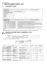
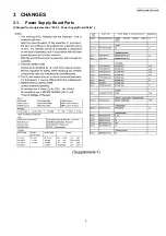
1 REPLACEMENT PARTS LIST
1.1.
REFERENCE CHART
1.2.
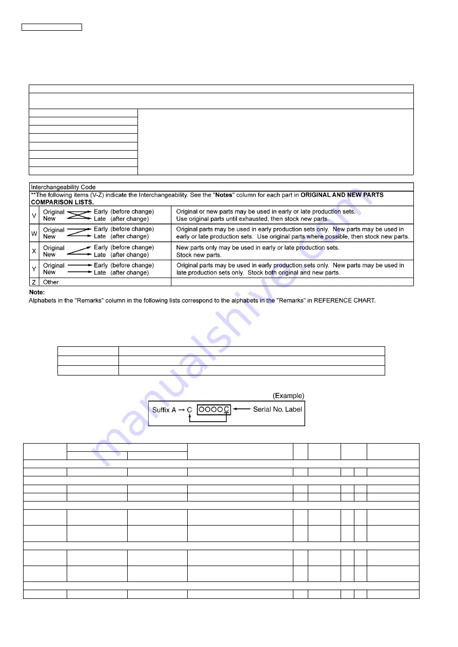
ORIGINAL AND NEW PARTS COMPARISON LISTS
Change of the Suffix Code
Serial No.Label tells you the suffix code as follows.
Reason for Change
*The following items (1-8) indicate the reason for change. See the “
Notes
” column for each part in
ORIGINAL AND NEW PARTS
COMPARISON LISTS.
1. Improve performance
*a
: To enhance the quality.
*c
: To share the parts with other models.
2. Change of material or dimension
3. To meet approved specification
4. Standardization
5. Addition
6. Deletion
7. Correction
8. Other
Suffix Code
Reasons of change
A
→
B
To change software version and checksum.
B
→
C
Head holder modification for printing light countermeasure.
Ref. No.
Part No.
Part Name & Description
Pcs/
Set
Remarks
Notes
Time of Change
Original (Old)
New
(Suffix)
OPERATION PANEL SECTION
1
PFGV1022Z
PFGV1022Y
TRANSPARENT PLATE
1
*a
1
W
---
UPPER CABINET SECTION
93
PFHR1715Z
PFHR1715Y
GUIDE, HOLDER HEAD/L
1
*a
1
W
B to C
94
PFHR1716Z
PFHR1716Y
GUIDE, HOLDER HEAD/R
1
*a
1
W
B to C
DIGITAL BOARD PARTS (for KX-FP701CX)
IC6
PFWIFP701CX
PFWIFP701CX1
IC (ROM) (Change 1)
[Program Ver. GB21CN
→
GB21CP]
1
*a
1
W
A to B
IC6
PFWIFP701CX1
PFWIFP701CX2
IC (ROM) (Change 2)
[Program Ver. GB21CP
→
GB21CQ]
1
*a
1
W
---
DIGITAL BOARD PARTS (for KX-FP702CX)
IC6
PFWIFP702CX
PFWIFP702CX1
IC (ROM) (Change 1)
[Program Ver. GBG1CN
→
GBG1CP]
1
*a
1
W
A to B
IC6
PFWIFP702CX1
PFWIFP702CX2
IC (ROM) (Change 2)
[Program Ver. GBG1CP
→
GBG1CQ]
1
*a
1
W
---
INTERFACE BOARD PARTS
F401, F402
K5H122200005
K5H122Y00002
FUSE
2
*c
4
V
---


