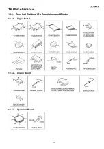
141
KX-FT932BR-B
16.2. How to Replace the Flat Package IC
Even if you do not have the special tools (for example, a spot heater) to remove the Flat IC, with some solder (large amount), a
soldering iron and a cutter knife, you can easily remove the ICs that have more than 100 pins.
16.2.1. Preparation
• PbF (: Pb free) Solder
• Soldering Iron
Tip Temperature of 700
°
F ± 20
°
F (370
°
C ± 10
°
C)
Note:
We recommend a 30 to 40 Watt soldering iron. An expert may be able to use a 60 to 80 Watt iron where someone with
less experience could overheat and damage the PCB foil.
• Flux
Recommended Flux: Specific Gravity
→
0.82.
Type
→
RMA (lower residue, non-cleaning type)
Note:
See
About Lead Free Solder (PbF: Pb free)
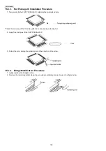
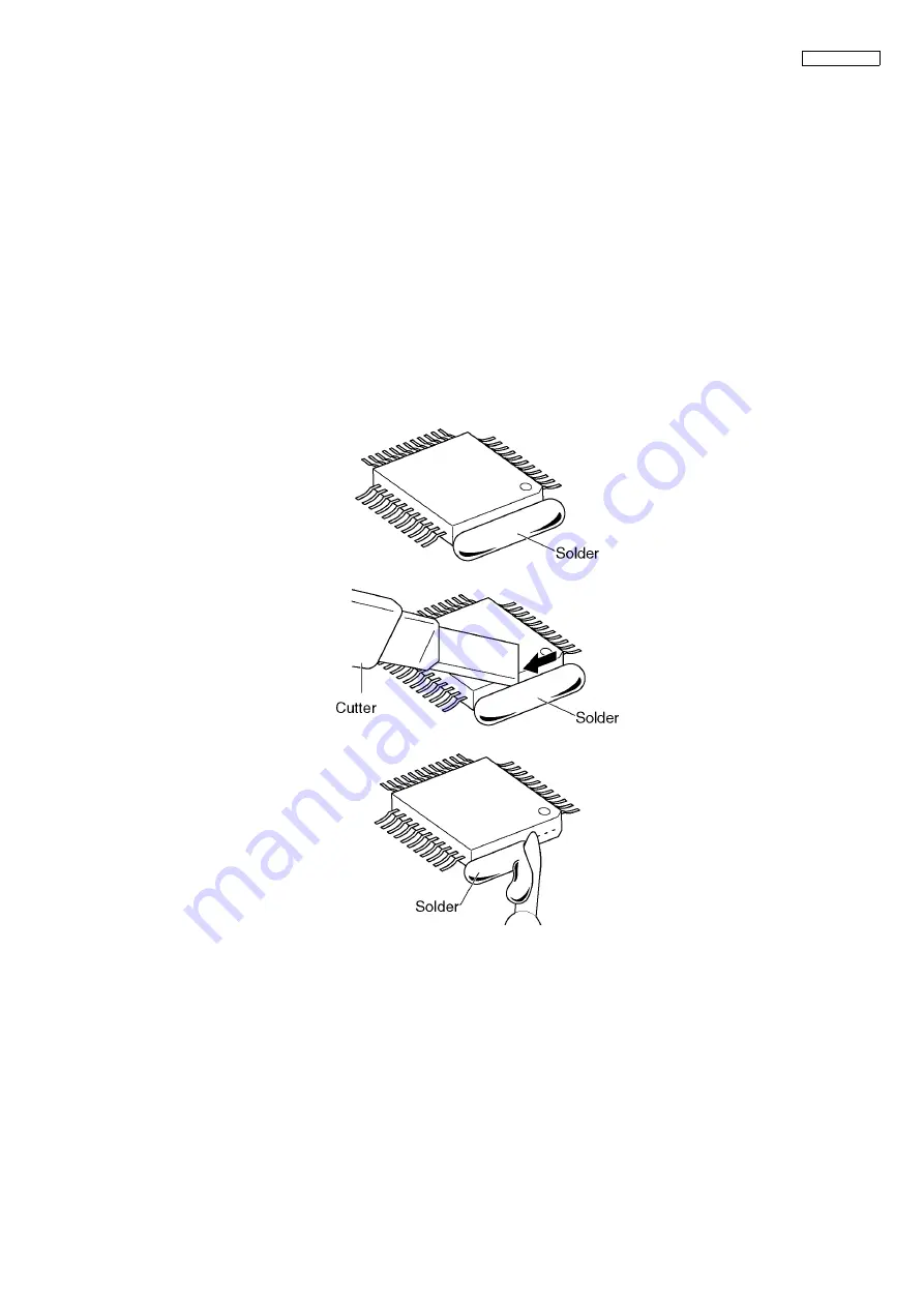
16.2.2. Flat Package IC Removal Procedure
1. Put plenty of solder on the IC pins so that the pins can be completely covered.
Note:
If the IC pins are not soldered enough, you may give pressure to the P.C. board when cutting the pins with a cutter.
2. Make a few cuts into the joint (between the IC and its pins) first and then cut off the pins thoroughly.
3. While the solder melts, remove it together with the IC pins.
When you attach a new IC to the board, remove all solder left on the land with some tools like a soldering wire. If some solder is left
at the joint on the board, the new IC will not be attached properly.
Summary of Contents for KX-FT932BR-B
Page 11: ...11 KX FT932BR B 6 Technical Descriptions 6 1 Connection Diagram ...
Page 21: ...21 KX FT932BR B 6 4 2 Block Diagram ...
Page 23: ...23 KX FT932BR B ...
Page 61: ...61 KX FT932BR B 11 2 2 Service Mode Example of a printed out list ...
Page 67: ...67 KX FT932BR B ...
Page 68: ...68 KX FT932BR B CROSS REFERENCE Test Mode P 54 ...
Page 69: ...69 KX FT932BR B CROSS REFERENCE Test Mode P 54 ...
Page 70: ...70 KX FT932BR B CROSS REFERENCE Test Mode P 54 ...
Page 71: ...71 KX FT932BR B ...
Page 73: ...73 KX FT932BR B ...
Page 74: ...74 KX FT932BR B ...
Page 75: ...75 KX FT932BR B CROSS REFERENCE Test Mode P 54 ...
Page 102: ...102 KX FT932BR B NG Wave pattern Note Refer to NG Example P 107 ...
Page 104: ...104 KX FT932BR B I O and Pin No Diagram ...
Page 106: ...106 KX FT932BR B ...
Page 107: ...107 KX FT932BR B 12 5 5 3 NG Example ...
Page 111: ...111 KX FT932BR B 12 5 7 2 Troubleshooting Flow Chart ...
Page 116: ...116 KX FT932BR B 12 5 11 Thermal Head Section Refer to Thermal Head P 22 ...
Page 117: ...117 KX FT932BR B 13 Service Fixture Tools ...
Page 120: ...120 KX FT932BR B 14 2 Disassembly Procedurel 14 2 1 How to Remove the Operation Panel Block ...
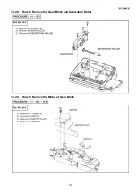
Page 121: ...121 KX FT932BR B 14 2 2 How to Remove the Operation Board LCD and Platen Roller ...
Page 122: ...122 KX FT932BR B 14 2 3 How to Remove the Separation Holder and Document Feed Support ...
Page 123: ...123 KX FT932BR B 14 2 4 How to Remove the Image Sensor CIS and Feed Roller ...
Page 124: ...124 KX FT932BR B 14 2 5 How to Remove the Lock Lever and Thermal Head ...
Page 125: ...125 KX FT932BR B 14 2 6 How to Remove the Bottom Frame ...
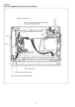
Page 128: ...128 KX FT932BR B 14 2 10 Installation Position of the Lead Wires ...
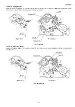
Page 134: ...134 KX FT932BR B 15 2 3 Mechanical Movements in the Main Operations 15 2 3 1 Idle Status ...
Page 136: ...136 KX FT932BR B 15 2 3 4 Copying CROSS REFERENCE Sensor Section P 114 ...
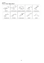
Page 140: ...140 KX FT932BR B 16 1 4 Power Supply Board ...
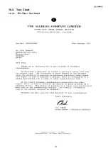
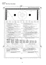
Page 143: ...143 KX FT932BR B 16 3 Test Chart 16 3 1 ITU T No 1 Test Chart ...
Page 144: ...144 KX FT932BR B 16 3 2 ITU T No 2 Test Chart ...
Page 145: ...145 KX FT932BR B MEMO ...
Page 152: ...152 KX FT932BR B MEMO ...
Page 161: ...161 KX FT932BR B MEMO ...
Page 163: ...163 KX FT932BR B 20 1 2 Upper Cabinet Section ...
Page 164: ...164 KX FT932BR B 20 1 3 Lower Cabinet Section ...
Page 165: ...165 KX FT932BR B 20 1 4 Gear Block Section ...
Page 166: ...166 KX FT932BR B 20 1 5 Screws ...
Page 167: ...167 KX FT932BR B 20 1 6 Accessories and Packing Materials ...

