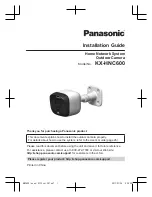

Installation Guide
Home Network System
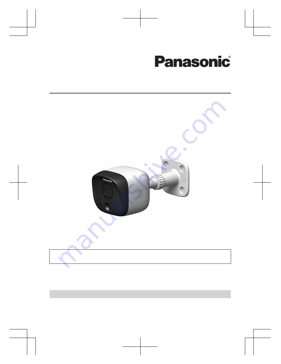
Outdoor Camera
Model No.
KX-HNC600
Thank you for purchasing a Panasonic product.
This document explains how to install the outdoor camera properly.
For details about how to use the system, refer to the User’s Guide (page 26).
Please read this document before using the unit and save it for future reference.
For assistance, please contact us at 1-800-272-7033 or visit our Web site:
http://shop.panasonic.com/support
for customers in the U.S.A.
Please register your product: http://shop.panasonic.com/support
Printed in China
HNC600_(en_en)_0123_ver.201.pdf 1
2017/01/26 9:24:39