background image

Testing the window/

door sensor

You can check the window/door
sensor’s LED indicator and test the
performance of the window/door
sensor.

1

Remove the sensor unit cover.

2

Press 

M

N

 on the sensor unit.

3

Open and close the window or
door several times.

R

Make sure that the LED
indicator lights in green when
you close the window or door.

4

Press 

M

N

 again.

Note:

R

If the LED indicator lights in red
when the window or door is closed,
the window/door sensor is not
installed properly. Re-evaluate the
position of the sensor unit and
magnet unit (page 11).

Features available

when using the

[Home Network] app

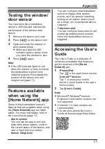
Some of the window/door sensor’s
features that are available when using
the 

[Home Network]

 app are listed

below. For more information, refer to
the User’s Guide (page 17).

Alarm system

You can use the app to arm and
disarm the alarm system, confirm
the current status of the sensor, and
view a log of previous events.

Sensor integration

You can configure the window/door
sensor to trigger other system
events, such as camera recording,
turning on an electric device (such
as a lamp), etc. (Appropriate device
required.)

Telephone alert

You can configure the system to call
a preprogrammed phone number
when the window/door sensor is
triggered.

Accessing the User’s

Guide

The User’s Guide is a collection of
online documentation that helps you
get the most out of the 

[Home

Network]

 app.

1

iPhone/iPad

Tap 

 in the app’s home screen.

Android™ devices

Tap   or press your mobile
device’s menu button in the app’s
home screen.

2

Tap 

[User’s Guide]

.

Note:

R

Microsoft

®

 Windows

®

 Internet

Explorer

®

 8 and earlier versions are

not supported.

R

Android 4.1 or later versions are
recommended.

R

You can also access the User’s
Guide at the web page listed below.

17

Appendix

Summary of Contents for KX-HNS101FX

Page 1: ...101FX Thank you for purchasing a Panasonic product This document explains how to install the window door sensor properly For details about how to use the system refer to the User s Guide page 17 Please read this document before using the unit and save it for future reference ...

Page 2: ...rt names and functions 8 LED indicator 8 Setup overview 8 Inserting the battery 9 Registering the window door sensor 9 Changing the sensor type 10 Wireless communication range 10 Temporary placement 11 Installation 14 Appendix Testing the window door sensor 17 Features available when using the Home Network app 17 Accessing the User s Guide 17 Specifications 18 2 Table of Contents ...

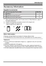
Page 3: ... magnet unit A B C Other information R Design and specifications are subject to change without notice R The illustrations in these instructions may vary slightly from the actual product Trademarks R iPhone and iPad are trademarks of Apple Inc registered in the U S and other countries R Android is a trademark of Google Inc R Microsoft Windows and Internet Explorer are either registered trademarks o...

Page 4: ...lled devices such as automatic doors and fire alarms Radio waves emitted from this product may cause such devices to malfunction resulting in an accident R Keep small parts magnet unit magnet unit cover screws etc out of the reach of children There is a risk of swallowing In the event they are swallowed seek medical advice immediately Operating safeguards R Do not disassemble the product Medical R...

Page 5: ...ating and rupture Do not attempt to use a battery if it is leaking R Exercise care when handling the batteries Do not allow conductive materials such as rings bracelets or keys to touch the batteries otherwise a short circuit may cause the batteries and or the conductive material to overheat and cause burns Important safety instructions When using your product basic safety precautions should alway...

Page 6: ...interference Move away from the electrical appliances Other information CAUTION Risk of explosion if battery is replaced by an incorrect type Dispose of used batteries according to the instructions Routine care R Wipe the outer surface of the product with a soft moist cloth R Do not use benzine thinner or any abrasive powder Disposal of Old Equipment and Batteries Only for European Union and count...

Page 7: ...are only valid in the European Union If you wish to discard these items please contact your local authorities or dealer and ask for the correct method of disposal Note for the battery symbol This symbol B might be used in combination with a chemical symbol In this case it complies with the requirement set by the Directive for the chemical involved Note for the battery removal procedure Refer to In...

Page 8: ...ndicator off by pressing M N again as soon as possible otherwise battery life may be reduced Indicator Status Green lit Window door is closed Red lit Window door is open Red blinking Sensor is out of range of the hub Green blinking slowly Registration mode You pressed and held M N Off No battery power Note R The LED indicator does not indicate sensor status if the sensor has not been registered pa...

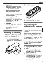
Page 9: ... 1 Remove the sensor unit cover R Lift from the indented area A and open the sensor unit cover B 1 2 2 Insert the battery 3 Attach the sensor unit cover Registering the window door sensor This procedure is not required for devices that were included as part of a bundle Before you can use the window door sensor it must be registered to the hub If you purchased devices separately i e not as part of ...

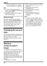
Page 10: ... Guide page 17 Wireless communication range The wireless communication range of each device in the system from the hub is approximately 50 m indoors and approximately 300 m outdoors Wireless communication may be unreliable when the following obstacles are located between the hub and other devices R Metal doors or screens R Walls containing aluminium sheet insulation R Walls made of concrete or cor...

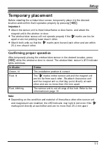
Page 11: ...the window door sensor in the desired location press M N while the window or door is closed The window door sensor s LED indicator lights as follows Indicator Status Green lit The installation position is correct Red lit The marks on the sensor unit and the magnet unit are too far from each other Re attach the sensor unit and the magnet unit so that they point directly at each other and are no mor...

Page 12: ...h other Result When you press M N A the LED indicator lights in green B Incorrect 2 3 4 A B Red 2 marks are aligned but units are too far apart 3 marks are aligned but window frame is too thick units are too far apart 4 marks are not aligned Magnet unit is too high Result When you press M N A the LED indicator lights in red B 12 Setup ...

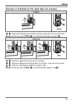
Page 13: ...ch other Result When you press M N A the LED indicator lights in green B Incorrect 2 3 4 A B Red 2 marks are aligned but units are too far apart 3 marks are aligned but window frame is too thick units are too far apart 4 marks are not aligned Magnet unit is too high Result When you press M N A the LED indicator lights in red B 13 Setup ...

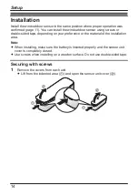
Page 14: ...ng on your preference or the material of the installation area Note R When installing make sure the battery is inserted properly and the sensor unit cover is completely closed R Use screws when installing on a wooden surface Do not use double sided tape Securing with screws 1 Remove the covers from each unit R Lift from the indented area A and open the sensor unit cover B 1 2 1 2 14 Setup ...

Page 15: ...86 2 mm Magnet unit Attach the magnet unit 3 Screws 4 24 4 mm 2 4 1 1 3 3 5 3 Attach the covers Important R 5 Align the marks on the sensor unit and the magnet unit so that they point directly at each other and are no more than 25 4 mm apart 15 Setup ...

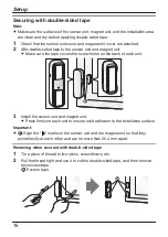
Page 16: ...the screw holes on the back of each unit 5 3 Install the sensor unit and magnet unit R Press firmly on each unit to ensure solid adhesion to the installation surface Important R 5 Align the marks on the sensor unit and the magnet unit so that they point directly at each other and are no more than 25 4 mm apart Removing when secured with double sided tape 1 Tie a piece of thread to two sticks screw...

Page 17: ... Alarm system You can use the app to arm and disarm the alarm system confirm the current status of the sensor and view a log of previous events Sensor integration You can configure the window door sensor to trigger other system events such as camera recording turning on an electric device such as a lamp etc Appropriate device required Telephone alert You can configure the system to call a preprogr...

Page 18: ...2 CR15H270 1 3 0 V 850 mAh R Operating conditions 10 C 40 C R Battery life Up to 2 years when window door is opened and closed 10 times a day in an environment of 25 C when using a 3 0 V 850 mAh battery The battery life differs depending on the capacity of the battery used R Dimensions height width depth Sensor unit Approx 102 mm 31 mm 22 mm Magnet unit Approx 37 mm 14 mm 14 mm R Mass weight Senso...

Page 19: ...19 Notes ...
Page 20: ... a record of the following information to assist with any repair under warranty Serial No Date of purchase found inside the sensor unit Name and address of dealer Attach your purchase receipt here Panasonic Corporation 2016 PNQP1187YA CC0216WK1126 ...

Reviews: