31
KX-NCP500GR
4.6.5.
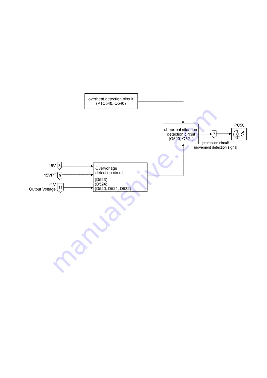
Protective Circuit Operation Section
Part 6 provides a description of the overvoltage/overheat protection circuits.
1. Abnormal State Detection Circuit
The abnormality detection circuit consists of the transistor Q520/Q521 thyristor circuits.
If power operation becomes abnormal and a signal is transmitted to the abnormality detection circuit, Q521 is turned on, cur-
rent flows to the diode of PC50 and is transmitted to the control circuit of the main converter, thereby shutting down main con-
verter operation. (See Part 2)
2. Overheat Protection Circuit
When temperature inside the power source rises to an abnormal temperature, the resistance of posister PTC540 rises, tran-
sistor Q540 is turned on, and the signalis transmitted to the abnormality detection circuit via D542.
3. Overvoltage Protection Circuit
If voltage of either 15V, 15VPT or 41V output becomes excessively high, the voltage is transmitted to the abnormality detec-
tion circuit via Zener diode D526.
Summary of Contents for KX-NCP500GR
Page 9: ...9 KX NCP500GR ...
Page 12: ...12 KX NCP500GR 4 2 Power Supply Block Diagram ...
Page 20: ...20 KX NCP500GR 4 5 5 System Control 4 5 5 1 System Control Block Diagram ...
Page 21: ...21 KX NCP500GR 4 5 5 2 Voice TDM Highway Bus Block Diagram ...
Page 24: ...24 KX NCP500GR 4 5 6 2 EC Bus System Connection Diagram ...
Page 32: ...32 KX NCP500GR 5 Location of Controls and Components 5 1 Name and Locations ...
Page 36: ...36 KX NCP500GR ...
Page 53: ...53 KX NCP500GR 9 Troubleshooting Guide 9 1 IPCMPR Card 9 1 1 Startup ...
Page 54: ...54 KX NCP500GR ...
Page 55: ...55 KX NCP500GR ...
Page 56: ...56 KX NCP500GR ...
Page 57: ...57 KX NCP500GR 9 1 1 1 Main alarm light turns on ...
Page 58: ...58 KX NCP500GR 9 1 1 2 SD card access light does not flash ...
Page 60: ...60 KX NCP500GR ...
Page 61: ...61 KX NCP500GR 9 1 1 6 Option card cannot start up ...
Page 62: ...62 KX NCP500GR 9 1 2 Phone Call 9 1 2 1 The path cannot connect ...
Page 63: ...63 KX NCP500GR 9 1 2 2 Noise is created ...
Page 64: ...64 KX NCP500GR 9 1 3 Paging 9 1 3 1 Noise is created ...
Page 65: ...65 KX NCP500GR ...
Page 66: ...66 KX NCP500GR 9 1 4 Using MOH ...
Page 67: ...67 KX NCP500GR ...
Page 68: ...68 KX NCP500GR 9 1 5 LAN 9 1 5 1 LAN Connection ...
Page 69: ...69 KX NCP500GR 9 1 6 ESVM 9 1 6 1 ESVM function record play ...
Page 70: ...70 KX NCP500GR ...
Page 71: ...71 KX NCP500GR 9 1 7 RS 232C 9 1 7 1 RS 232C Connection ...
Page 72: ...72 KX NCP500GR 9 1 8 SD card IF ...
Page 73: ...73 KX NCP500GR 9 1 9 Other ...
Page 75: ...75 KX NCP500GR 9 2 1 1 Defective parts list ...
Page 78: ...78 KX NCP500GR 9 2 4 15VPT output voltage only not output 9 2 4 1 Defective parts list ...
Page 79: ...79 KX NCP500GR 9 2 5 41V output voltage only not output 9 2 5 1 Defective parts list ...
Page 80: ...80 KX NCP500GR 10 Service Fixture Tools 10 1 Extension Boards for Servicing ...
Page 87: ...87 KX NCP500GR 12 2 3 Power Supply Board ...
Page 129: ...129 KX NCP500GR Waveform 7 Waveform 8 Waveform 9 159 984MHz 13 824MHz 16 384MHz ...
Page 145: ...145 KX NCP500GR 16 2 Cabinet and Electrical Parts Location ...
Page 146: ...146 KX NCP500GR 16 3 Accessories and Packing Material ...


