Items
Adjustment
Point
Procedure*
Check
(C)
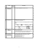
VBACK Status
Confirmation
-
1. Confirm that the voltage between J102 and GND is 0V ± 0.4V.
IC2,Q8,C23,
C24,C25,C26,
C27,C38,R33,
R36,D5,C41,
R41,R42,Q9,
C40,D4,R33,
X1,C32,C33
(D)
*
BBIC Selftest
-
1. BBIC Selftest (Execute the command "getchk").
2. Confirm the returned checksum value.
Connection of checksum value and program number is shown
below.
IC2,X1,C32,
(E)
*
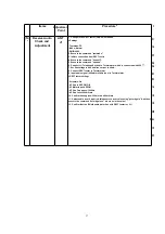
BBIC Clock
Adjustment
TP1
1. Execute the command "deactmac".
2. Execute the command "conttx".
3. Input Command “rdeeprom_00_00_02”, then you can confirm the current value.
4. Adjust the frequency of TP1 executing the command "setfreq 00 xx (where xx is the
value)" so that the reading of the frequency counter is 10.368000MHz ± 3Hz.
IC2,IC3,L1,
C48,X1,C32,
(F)
*
Hookswitch
Check with DC
Characteristics
-
1. Connect J1 (Telephone Socket) to Tel-simulator which is connected with 600 .
2. Set line voltage to 48V at on hook condition and line current to 40mA.
3. Execute the command "hookoff"
4. Confirm that the line current is 40mA ± 5mA.
5. Execute the command "hookon".
6. Confirm that the line current is 0mA + 2mA.
IC2,R7,R8,
R9,R10,R77,
Q2,Q3,D2,
32
Summary of Contents for KX-TCD400GC
Page 46: ...18 FREQUENCY TABLE MHz 46 ...
Page 52: ...24 CPU DATA BASE UNIT 24 1 IC2 BBIC 52 ...
Page 56: ...45 MICP A I 56 ...
Page 60: ...60 ...
Page 61: ...28 CABINET AND ELECTRICAL PARTS LOCATION HANDSET 29 ACCESSORIES AND PACKING MATERIALS 61 ...
Page 62: ...30 TERMINAL GUIDE OF THE ICs TRANSISTORS AND DIODES 30 1 Base Unit 30 2 Handset 62 ...
Page 91: ...4 1 5 8 PbF 1 28 18 IC3 IC2 IC1 11 64 1 16 17 32 49 48 33 Marked ...
Page 93: ...Marked PbF IC1 IC2 100 80 5 8 4 1 50 51 30 31 1 11 18 1 28 IC3 ...

