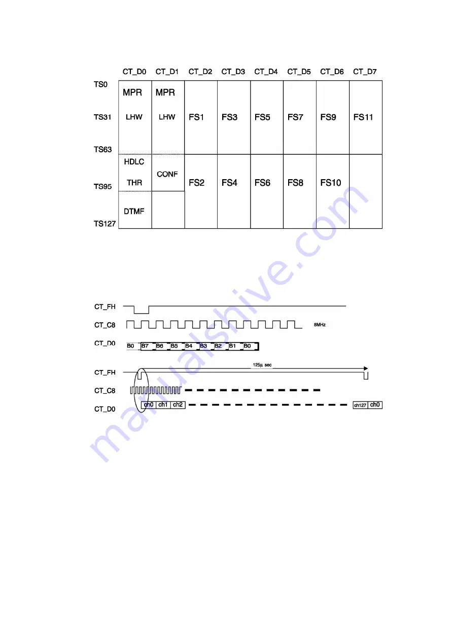
In the line card, the CT_D line number, which is output in accordance with the inserted slot, and
the time slot are assigned on a software base.
For the detail of output slot for each card, refer to the service manual of card.
8.2.4. Back Board Signaling
Back board waveform of TDM bus for voice
8.3. BACK BOARD SIGNAL CONNECTION DIAGRAM
8.3.1. CT Bus System Connection Diagram
24
Summary of Contents for KX-TDA100AL
Page 9: ...5 2 SYSTEM COMPONENTS 9 ...
Page 13: ...13 ...
Page 15: ... Null slot Null slot is not available for any optional service card RUN Indicator 15 ...
Page 19: ...3 Remove the Hook And remove the Top Cover 4 Remove nine Screws B 5 Remove the Back Cover 19 ...
Page 22: ...8 2 2 Voice TDM Highway Bus Block Diagram 22 ...
Page 23: ...8 2 3 Voice Bus Logical Assignment 23 ...
Page 25: ...8 3 2 EC Bus System Connection Diagram 25 ...
Page 26: ...8 3 3 System Control and Analog Signal Connection Diagram 26 ...
Page 27: ...8 3 4 Power Supply System Connection Diagram 27 ...
Page 30: ...30 ...
Page 41: ...41 ...
Page 42: ...42 ...
Page 43: ...43 ...
Page 44: ...44 ...
Page 45: ...11 1 2 Phone Call 45 ...
Page 46: ...11 1 3 Paging 46 ...
Page 47: ...47 ...
Page 48: ...48 ...
Page 49: ...11 1 4 MOH Using 49 ...
Page 50: ...50 ...
Page 51: ...51 ...
Page 52: ...11 1 5 USB Connection 52 ...
Page 53: ...53 ...
Page 54: ...11 1 6 RS 232C Connection 54 ...
Page 55: ...55 ...
Page 56: ...11 1 7 SD Card I F 11 1 8 Other 56 ...
Page 57: ...12 DIAGNOSIS 12 1 DIAGNOSIS FEATURES 57 ...
Page 66: ...7 Click Card Test 8 Click OK 9 Click Cancel 13 IC DATA 13 1 IC101 66 ...
Page 76: ...76 ...
Page 77: ...16 1 EXTENSION BOARDS FOR SERVICING 17 ACCESSORIES AND PACKING MATERIALS 77 ...
Page 100: ......
Page 110: ...Waveform 7 Waveform 8 20MHz 12MHz ...
Page 118: ......
Page 119: ......
Page 120: ......
Page 121: ......
Page 122: ......
Page 123: ......
Page 124: ......
Page 125: ......


