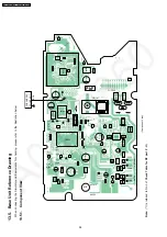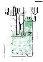
13.3. X801 (Base Unit), X201 (Handset) Check
Equipment: Frequency counter
Check Point for measurement: BCK
Checking tolerance: 13.824MHz ± 100Hz
13.3.1. Check and Adjust X801 (Base Unit) Frequency
1. Set up Base Unit in TEST mode.
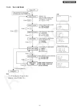
2. Press following keys in order to Adjust Crystal mode. [INTERCOM], [INTERCOM], [INTERCOM], [1] or [2], [2], [2], [1]
* Check BCK frequency.
3. If the BCK frequency is out of the checking tolerance (± 100Hz), adjust to Adjustment tolelance (± 30Hz) by pressing [ ] or [ ]
key.
Adjustment Tolerance: 13.824MHz ± 30Hz
4. Press [INTERCOM] key to write the new frequency factor in Memory.
5. Turn the power off. Then this value is available.
Cross Reference:
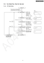
TX Burst Mode and Adjust X’tal Mode
(P.46)
13.3.2. Check and Adjust X201 (Handset) Frequency
1. Set DC power supply to 3.9V.
2. Set up Handset in TEST mode (Adjustment flow).
3. Press [1] key to Adjust Crystal mode. (“Clock Adj” is displayed on LCD)
* Check BCK frequency.
4. If the BCK frequency is out of the checking tolerance (± 100Hz), adjust to Adjustment tolelance (± 30Hz) by pressing [ ] or [ ]
key.
Adjustment Tolerance: 13.824MHz ± 30Hz
5. Press [TALK] key to write the new frequency factor in EEPROM.
6. Turn the power off. Then this value is available.
Cross Reference:
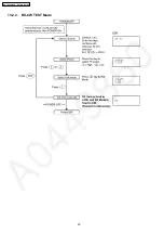
Adjustment flow (X’tal mode and Batt Low mode)
(P.52)
13.4. Adjust Battery Low Detector Voltage (Handset)
After handset´s DSP (IC201) or EEPROM (IC202) replacement (*1), Re-writing Battery Low voltage to EEPROM is required.
Follow
Test Mode Flow Chart for Handset
(P.49).
DC power supply and DC voltmeter require the adjustment below.
1. Set DC power supply to 3.9V.
2. Set up handset in test mode (Adjustment flow).
3. Press [1] key and [OFF] key twice to Adjust Batt Low mode. ("Bat Adj" is displayed on LCD)
4. Change voltage to 3.50V accurately for the DC power supply.
* Check voltage at P.C. board test points because some voltage drops occur due to the usage of long or thin cable.
5. Press [TALK] key to write voltage value in EEPROM.
6. Turn the power off. Then this value is available.
Note:
For connection of DC power source and voltmeter, see
Handset Reference Drawing
(P.56).
53
KX-TG2340JXS / KX-TGA236JXS
Summary of Contents for KX-TG2340JXS
Page 8: ...4 1 4 Battery Information 4 2 Battery Replacement 8 KX TG2340JXS KX TGA236JXS ...
Page 9: ...5 LOCATION OF CONTROLS 5 1 Base unit 9 KX TG2340JXS KX TGA236JXS ...
Page 10: ...5 2 Handset 10 KX TG2340JXS KX TGA236JXS ...
Page 12: ...7 SETTINGS 7 1 Connections 12 KX TG2340JXS KX TGA236JXS ...
Page 13: ...7 2 Connecting an Optional Headset 13 KX TG2340JXS KX TGA236JXS ...
Page 14: ...7 3 Function Menu Table Cross Reference Direct Commands P 19 14 KX TG2340JXS KX TGA236JXS ...
Page 15: ...7 4 Date and Time 15 KX TG2340JXS KX TGA236JXS ...
Page 16: ...7 5 Dialing Mode 7 6 Line Mode 16 KX TG2340JXS KX TGA236JXS ...
Page 17: ...7 7 Voice Enhancer Technology 7 8 Ringer Tone 17 KX TG2340JXS KX TGA236JXS ...
Page 18: ...18 KX TG2340JXS KX TGA236JXS ...
Page 19: ...7 9 Direct Commands 19 KX TG2340JXS KX TGA236JXS ...
Page 20: ...8 1 Answering Calls 8 OPERATION 20 KX TG2340JXS KX TGA236JXS ...
Page 21: ...8 2 For Call Waiting Service Users 8 3 Using the PAUSE Key 21 KX TG2340JXS KX TGA236JXS ...
Page 22: ...8 4 Dial Lock 22 KX TG2340JXS KX TGA236JXS ...
Page 24: ...8 5 FLASH Button 24 KX TG2340JXS KX TGA236JXS ...
Page 25: ...8 6 Phone Book 8 6 1 Storing Names and Numbers 25 KX TG2340JXS KX TGA236JXS ...
Page 26: ...26 KX TG2340JXS KX TGA236JXS ...
Page 27: ...8 6 2 Dialing from the Phone Book 27 KX TG2340JXS KX TGA236JXS ...
Page 28: ...8 6 3 Chain Dial 28 KX TG2340JXS KX TGA236JXS ...
Page 31: ...31 KX TG2340JXS KX TGA236JXS ...
Page 35: ...11 ASSEMBLY INSTRUCTIONS 11 1 Fix the LCD to P C Board Handset 35 KX TG2340JXS KX TGA236JXS ...
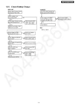
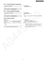
Page 39: ...Note DSP is IC501 12 5 Check Battery Charge 39 KX TG2340JXS KX TGA236JXS ...
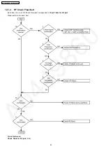
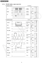
Page 44: ...12 7 4 RF DSP interface signal wave form 44 KX TG2340JXS KX TGA236JXS ...
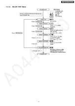
Page 47: ...13 1 2 RX CW TEST Mode 47 KX TG2340JXS KX TGA236JXS ...
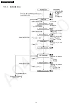
Page 48: ...13 1 3 Test Link Mode 48 KX TG2340JXS KX TGA236JXS ...
Page 49: ...13 2 Test Mode Flow Chart for Handset 13 2 1 TX Burst Mode 49 KX TG2340JXS KX TGA236JXS ...
Page 50: ...13 2 2 RX CW TEST Mode 50 KX TG2340JXS KX TGA236JXS ...
Page 76: ...20 SIGNAL ROUTE Each signal route is as follows 76 KX TG2340JXS KX TGA236JXS ...
Page 79: ...23 EXPLANATION OF IC TERMINALS RF Unit 23 1 IC901 79 KX TG2340JXS KX TGA236JXS ...
Page 82: ...25 CABINET AND ELECTRICAL PARTS Base Unit 82 KX TG2340JXS KX TGA236JXS ...
Page 83: ...26 CABINET AND ELECTRICAL PARTS Handset 83 KX TG2340JXS KX TGA236JXS ...
Page 84: ...27 ACCESSORIES AND PACKING MATERIALS 84 KX TG2340JXS KX TGA236JXS ...
Page 101: ...101 KX TG2340JXS KX TGA236JXS M T N KXTG2340JXS KXTGA236JXS ...

