29 REPLACEMENT PARTS
LIST
Note:
1. RTL (Retention Time Limited)
The marking (RTL) indicates that the Retention Time is
limited for this item.
After the discontinuation of this assembly in production, the
item will continue to be available for a specific period of
time. The retention period of availability is dependant on the
type of assembly, and in accordance with the laws
governing part and product retention. After the end of this
period, the assembly will no longer be available.
2. Important safety notice
Components identified by the
; mark indicates special
characteristics important for safety. When replacing any of
these components, only use specified manufacture´s parts.
3. The S mark means the part is one of some identical parts.
For that reason, it may be different from the installed part.
4. ISO code (Example: ABS-94HB) of the remarks column
shows quality of the material and a flame resisting grade
about plastics.
5. RESISTORS & CAPACITORS
Unless otherwise specified;
All resistors are in ohms (
Ω
) K=1000
Ω
, M=1000k
Ω
All capacitors are in MICRO FARADS (µF) P=µµF
*Type & Wattage of Resistor
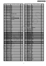
29.1. Base Unit
29.1.1. Cabinet and Electrical Parts
Ref.
No.
Part No.
Part Name & Description
Remarks
1
PQGG10252Y1
GRILLE, VM
ABS-HB
2
PQKE10131Z7
HANGER, HOOK LEVER
PC+ABS-
HB
3
PQUS10285Z
SPRING, HOOK
4
PQKE10134Z1
HANGER, HOOK KNOB
POM-HB
5
PQQT22575Z
LABEL, CHARGE
6
PQKM10624T1
CABINET BODY
PS-HB
7
PQWE10027Z
BATTERY TERMINAL
Ref.
No.
Part No.
Part Name & Description
Remarks
8
PQAS5P13Y
SPEAKER
9
PQBC10404V1
BUTTON, MESSAGE
AS-HB
10
PQHR11030Z
GUIDE, LED
ABS-HB
11
PQSA10098R
ANTENNA
12
PQSX10260Z
KEYBOARD SWITCH, VM
13
PQSX10261V
KEYBOARD SWITCH, DIAL
14
PQMG10025Z
RUBBER PARTS, MIC COVER
15
PQKF10611Y1
CABINET COVER
PS-HB
16
PQHA10018Z
RUBBER PARTS, FOOT CUSHION
17
PQKL10061Z1
STAND, WALL MOUNT
PS-HB
18
PQHA10017Z
RUBBER PARTS, LEG CUSHION
19
PQGT17697Z
NAME PLATE
20
PQHR11032Z
OPTIC
CONDUCTIVE
PARTS,
LED
LENS
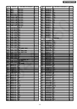
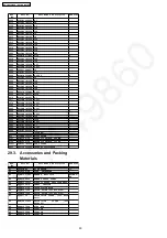
29.1.2. Main P.C. Board Parts
Note:
(*1) When you have replaced IC501 or IC701, adjust X801.
refer to
Check and Adjust X801 (Base Unit) Frequency
(P.53)
Ref.
No.
Part No.
Part Name & Description
Remarks
PCB1
PQWPG2340JXH
MAIN P.C.BOARD ASS´Y (RTL)
(ICs)
IC201
C0ABBA000025
IC
IC300
C0DBFGD00017
IC
IC301
C0DBAGZ00023
IC
IC501
C2HBBL000016
IC (*1)
IC601
C0CBAAD00054
IC
IC701
PQWIG2340JXH
IC (*1)
IC901
C1CB00001657
IC
(TRANSISTORS)
Q103
B1BBAP000011
TRANSISTOR(SI)
S
Q104
B1ADGP000008
TRANSISTOR(SI)
Q106
2SD1819A
TRANSISTOR(SI)
Q150
2SD1819A
TRANSISTOR(SI)
Q161
2SD0874AS
TRANSISTOR(SI)
Q201
2SD1819A
TRANSISTOR(SI)
Q202
UN5213
TRANSISTOR(SI)
S
Q301
B1DHCD000032
TRANSISTOR(SI)
Q350
2SD1758Q
TRANSISTOR(SI)
S
Q351
2SD1819A
TRANSISTOR(SI)
Q354
UN5213
TRANSISTOR(SI)
S
Q381
2SB1218A
TRANSISTOR(SI)
Q382
2SD1819A
TRANSISTOR(SI)
Q570
2SD1819A
TRANSISTOR(SI)
Q800
2SC39300CL
TRANSISTOR(SI)
(DIODES)
D101
PQVDMD5S
DIODE(SI)
D102
PQVDRLZ20A
DIODE(SI)
S
D103
MA111
DIODE(SI)
S
D161
PQVDRLZ2R0
DIODE(SI)
S
D303
B0JCME000035
DIODE(SI)
D306
B0JCME000035
DIODE(SI)
D376
MA8220
DIODE(SI)
S
D377
MA8220
DIODE(SI)
S
D381
B0ECKM000008
DIODE(SI)
D903
B0DCCD000011
DIODE(SI)
D904
B0DCCD000011
DIODE(SI)
DA101
MA147
DIODE(SI)
S
LED720
PQVDSML210L
DIODE(SI)
S
LED721
PQVDSML210L
DIODE(SI)
S
LED722
PQVDPY1112H
DIODE(SI)
S
LED724
PQVDSML210L
DIODE(SI)
S
(COILS)
L101
PQLQXF330K
COIL
S
L102
PQLQXF330K
COIL
S
L302
G1C220M00037
COIL
L376
G1C6R8MA0072
COIL
L377
G1C6R8MA0072
COIL
L401
G1C6R8MA0072
COIL
86
KX-TG2340JXS / KX-TGA236JXS
Summary of Contents for KX-TG2340JXS
Page 8: ...4 1 4 Battery Information 4 2 Battery Replacement 8 KX TG2340JXS KX TGA236JXS ...
Page 9: ...5 LOCATION OF CONTROLS 5 1 Base unit 9 KX TG2340JXS KX TGA236JXS ...
Page 10: ...5 2 Handset 10 KX TG2340JXS KX TGA236JXS ...
Page 12: ...7 SETTINGS 7 1 Connections 12 KX TG2340JXS KX TGA236JXS ...
Page 13: ...7 2 Connecting an Optional Headset 13 KX TG2340JXS KX TGA236JXS ...
Page 14: ...7 3 Function Menu Table Cross Reference Direct Commands P 19 14 KX TG2340JXS KX TGA236JXS ...
Page 15: ...7 4 Date and Time 15 KX TG2340JXS KX TGA236JXS ...
Page 16: ...7 5 Dialing Mode 7 6 Line Mode 16 KX TG2340JXS KX TGA236JXS ...
Page 17: ...7 7 Voice Enhancer Technology 7 8 Ringer Tone 17 KX TG2340JXS KX TGA236JXS ...
Page 18: ...18 KX TG2340JXS KX TGA236JXS ...
Page 19: ...7 9 Direct Commands 19 KX TG2340JXS KX TGA236JXS ...
Page 20: ...8 1 Answering Calls 8 OPERATION 20 KX TG2340JXS KX TGA236JXS ...
Page 21: ...8 2 For Call Waiting Service Users 8 3 Using the PAUSE Key 21 KX TG2340JXS KX TGA236JXS ...
Page 22: ...8 4 Dial Lock 22 KX TG2340JXS KX TGA236JXS ...
Page 24: ...8 5 FLASH Button 24 KX TG2340JXS KX TGA236JXS ...
Page 25: ...8 6 Phone Book 8 6 1 Storing Names and Numbers 25 KX TG2340JXS KX TGA236JXS ...
Page 26: ...26 KX TG2340JXS KX TGA236JXS ...
Page 27: ...8 6 2 Dialing from the Phone Book 27 KX TG2340JXS KX TGA236JXS ...
Page 28: ...8 6 3 Chain Dial 28 KX TG2340JXS KX TGA236JXS ...
Page 31: ...31 KX TG2340JXS KX TGA236JXS ...
Page 35: ...11 ASSEMBLY INSTRUCTIONS 11 1 Fix the LCD to P C Board Handset 35 KX TG2340JXS KX TGA236JXS ...
Page 39: ...Note DSP is IC501 12 5 Check Battery Charge 39 KX TG2340JXS KX TGA236JXS ...
Page 44: ...12 7 4 RF DSP interface signal wave form 44 KX TG2340JXS KX TGA236JXS ...
Page 47: ...13 1 2 RX CW TEST Mode 47 KX TG2340JXS KX TGA236JXS ...
Page 48: ...13 1 3 Test Link Mode 48 KX TG2340JXS KX TGA236JXS ...
Page 49: ...13 2 Test Mode Flow Chart for Handset 13 2 1 TX Burst Mode 49 KX TG2340JXS KX TGA236JXS ...
Page 50: ...13 2 2 RX CW TEST Mode 50 KX TG2340JXS KX TGA236JXS ...
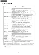
Page 76: ...20 SIGNAL ROUTE Each signal route is as follows 76 KX TG2340JXS KX TGA236JXS ...
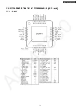
Page 79: ...23 EXPLANATION OF IC TERMINALS RF Unit 23 1 IC901 79 KX TG2340JXS KX TGA236JXS ...
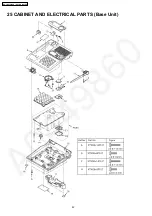
Page 82: ...25 CABINET AND ELECTRICAL PARTS Base Unit 82 KX TG2340JXS KX TGA236JXS ...
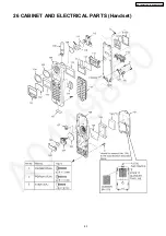
Page 83: ...26 CABINET AND ELECTRICAL PARTS Handset 83 KX TG2340JXS KX TGA236JXS ...
Page 84: ...27 ACCESSORIES AND PACKING MATERIALS 84 KX TG2340JXS KX TGA236JXS ...
Page 101: ...101 KX TG2340JXS KX TGA236JXS M T N KXTG2340JXS KXTGA236JXS ...

