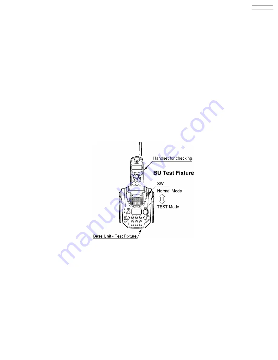
7.4.3. Base Unit Test Fixture for Handset
Switch to control normal mode and test mode on this BU Test Fixture.
Test Fixture has two modes.
1. TEST mode: (RF Power Low mode)
The switch of Test Fixture changed with TEST mode side.
Then Test Fixture is in TEST mode.
2. Normal mode: (RF Power Normal mode)
The switch of Test Fixture changed with TEST mode side.
Then Test Fixture is in Normal mode.
NOTE:
Audio is coming from Receiver whether switch is inserted or not.
This test simulates the handset is at very large distance from the base unit and the TX signal from base to handset is very small.
Procedure: First, place handset under test to charge (exchange security code), then remove handset from base after you hear
a beep. Press TALK button on handset and if it links with the base, then this handset sensitivity is OK. If a beep is not heard,
Replace the RF unit.
NOTE:
1) Only KX-TG2583/2563/2553/2403 with marks BU Test Fixture can be used for troubleshooting. Regular KX-
TG2583/2563/2553/2403 production samples do not have the software needed for troubleshooting.
37
KX-TG2559LBS
Summary of Contents for KX-TG2559LBS
Page 4: ...1 LOCATION OF CONTROLS 1 1 Base Unit 4 KX TG2559LBS ...
Page 5: ...1 2 Handset 5 KX TG2559LBS ...
Page 7: ...7 KX TG2559LBS ...
Page 9: ...3 2 Adding Another Phone 9 KX TG2559LBS ...
Page 11: ...3 3 4 Battery information 3 3 5 Standby mode The handset is off the base Unit 11 KX TG2559LBS ...
Page 12: ...3 4 Selecting the Dialing Mode 12 KX TG2559LBS ...
Page 13: ...3 5 Selecting the Line Mode 13 KX TG2559LBS ...
Page 14: ...4 OPERATION 4 1 Making Calls 14 KX TG2559LBS ...
Page 15: ...15 KX TG2559LBS ...
Page 16: ...4 2 Answering Calls 16 KX TG2559LBS ...
Page 17: ...4 3 Flash Button 17 KX TG2559LBS ...
Page 21: ...21 KX TG2559LBS ...
Page 22: ...4 4 4 Calling back from the caller list 22 KX TG2559LBS ...
Page 24: ...4 4 6 Storing caller list information in the directory 24 KX TG2559LBS ...
Page 26: ...5 DISASSEMBLY INSTRUCTIONS 26 KX TG2559LBS ...
Page 28: ...6 ASSEMBLY INSTRUCTIONS 6 1 Assembly the LCD to P C Board Handset 28 KX TG2559LBS ...
Page 29: ...6 2 How To Check Splash Resistance 29 KX TG2559LBS ...
Page 31: ...7 TROUBLESHOOTING GUIDE 31 KX TG2559LBS ...
Page 32: ...7 1 Check Power 32 KX TG2559LBS ...
Page 34: ...7 3 Check Link 34 KX TG2559LBS ...
Page 41: ...7 4 6 RF DSP Interface Signal Wave Form 41 KX TG2559LBS ...
Page 42: ...7 5 Check Handset Voice Transmission 7 6 Check Handset Voice Reception 42 KX TG2559LBS ...
Page 43: ...7 7 Check Call ID 43 KX TG2559LBS ...
Page 50: ...8 7 Frequency Table 50 KX TG2559LBS ...
Page 55: ...10 TERMINAL GUIDE OF IC S TRANSISTORS AND DIODES 10 1 Base Unit 10 2 Handset 55 KX TG2559LBS ...
Page 60: ...60 KX TG2559LBS ...
Page 67: ...15 CPU DATA Base Unit 15 1 IC501 68 KX TG2559LBS ...
Page 68: ...16 CPU DATA Handset 16 1 IC201 69 KX TG2559LBS ...
Page 69: ...17 EXPLANATION OF IC TERMINALS RF Unit Base Unit 17 1 IC101 70 KX TG2559LBS ...
Page 71: ...19 CABINET AND ELECTRICAL PARTS Base Unit 72 KX TG2559LBS ...
Page 72: ...20 CABINET AND ELECTRICAL PARTS Handset 73 KX TG2559LBS ...
Page 73: ...21 ACCESSORIES AND PACKING MATERIALS 74 KX TG2559LBS ...
Page 79: ...23 3 MEMO 80 KX TG2559LBS ...
Page 87: ...28 2 Flow Solder Side View IC551 B E C B E C KX TG2559LBS 88 ...
Page 90: ...91 KX TG2559LBS M H KXTG2559LBS Printed in Japan ...


