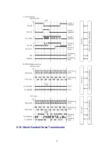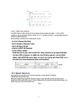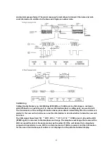
10.2.1. TDD Frame Format
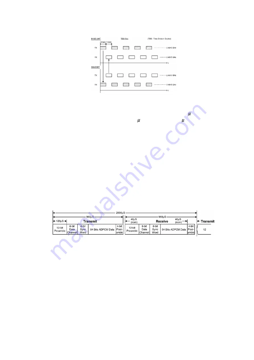
The TDD frame is 2mS in length, and is composed of two symmetrical 960
S TX and RX
subframes. Each subframe contains 96 bits of 10
S duration, with 40
S guard times between
both TX and RX subframes.
Each subframe consists of the following five fields:
- A 12-bit Preamble field
- An 8-bit Data Channel field
- An 8-bit Sync Word
- A 64-bit ADPCM Payload
- A 4-bit Post-amble
Both the 8-bit sync word and 8-bit data channel are programmable
via the DSP interface. In addition, the 64-bit payload can be filled
either with ADPCM voice data, or can be used by the host DSP as a
fast data channel between base and handset.
10.3. Spread Spectrum
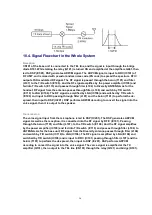
Transmission and reception are operated using the spread spectrum method.
DSS (Digital Spread Spectrum)
Mixing the original signal with the pseudo random noise code (PN code) works the spread
spectrum. In this system PN code is 15 chip. Although the band width is spread fifteen times, the
power level per channel becomes lower.
Fig. 8
55
Summary of Contents for KX-TG2583S
Page 3: ...3 ...
Page 4: ...1 2 Handset 2 DISPLAYS 4 ...
Page 5: ...3 SETTINGS 3 1 Connections 5 ...
Page 6: ...3 2 Adding Another Phone 6 ...
Page 7: ...3 3 Battery Charge 3 3 1 Battery strength 3 3 2 Recharge 7 ...
Page 8: ...3 3 3 Battery information 3 4 Selecting the Dialing Mode 8 ...
Page 9: ...3 5 Selecting the Line Mode 9 ...
Page 10: ...4 PREPARING THE ANSWERING SYSTEM 4 1 Day and Time Adjustment 10 ...
Page 11: ...11 ...
Page 12: ...5 OPERATION 5 1 Making Calls 5 1 1 With the Handset 12 ...
Page 13: ...13 ...
Page 14: ...5 1 2 With the Base Unit Digital Duplex Sperkerphone 14 ...
Page 15: ...15 ...
Page 16: ...5 2 Answering Calls 16 ...
Page 17: ...5 3 Flash Button 17 ...
Page 18: ...5 4 Listening to Message 18 ...
Page 19: ...19 ...
Page 22: ...5 5 3 Viewing the caller list 22 ...
Page 23: ...23 ...
Page 25: ...5 5 5 2 With the base unit 25 ...
Page 26: ...5 5 6 Storing caller list information in the directory 26 ...
Page 27: ...5 5 7 Erasing caller list information 27 ...
Page 28: ...28 ...
Page 29: ...6 DISASSEMBLY INSTRUCTIONS 29 ...
Page 30: ...30 ...
Page 32: ...7 2 Asseembly the LCD to P C Board Handset 32 ...
Page 33: ...7 3 How To Check Splash Resistance 33 ...
Page 36: ...8 1 Check Power 36 ...
Page 37: ...8 2 Error Message Table NOTE Flash memory is IC571 DSP is IC501 37 ...
Page 38: ...8 3 Check Record 8 4 Check Playback 8 5 Check SP phone Voice Transmission 38 ...
Page 39: ...8 6 Check SP phone Voice Reception 8 7 Check Battery Charge 39 ...
Page 48: ...8 10 Check Handset Voice Transmission 48 ...
Page 49: ...8 11 Check Handset Voice Reception 49 ...
Page 50: ...8 12 Check Call ID 50 ...
Page 51: ...9 TEST MODE AND ADJUSTMENT 9 1 Test Mode Flow Chart for Base Unit 51 ...
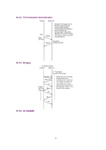
Page 57: ...10 5 EXPLANATION OF DSP DATA COMMUNICATION 10 5 1 Calling 57 ...
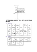
Page 58: ...10 5 2 To Terminate Communication 10 5 3 Ringing 10 5 4 ID CHANGE 58 ...
Page 59: ...11 TERMINAL GUIDE OF IC S TRANSISTORS AND DIODES 11 1 Base Unit 11 2 Handset 59 ...
Page 75: ...17 CPU DATA Handset 17 1 IC201 75 ...
Page 76: ...18 EXPLANATION OF IC TERMINALS RF Unit Base Unit 18 1 IC101 76 ...
Page 77: ...77 ...
Page 78: ...19 HOW TO REPLACE FLAT PACKAGE IC 19 1 Preparation SOLDER 78 ...
Page 81: ...81 ...
Page 82: ...21 CABINET AND ELECTRICAL PARTS Handset 82 ...
Page 103: ... Ýïïð Ýïðë Ýïïí Ýïïî Ýïðç Ýïïì Ýïðï Ýïðê ...
Page 104: ......
Page 106: ...ÍÐ ØÔÜ Í ð ç è é ê ë ì í î ï ÝÔÎ ÐßË ÚÔÍ ÎÜÔ ÔÝÌ ÎÒÙ ÛÒÌ ÛÈÌ ÜÉÒ Î ÙØÌ ËÐ ÍÌÐ ÓÍÙ ÔÛÚÌ ...
Page 108: ... Ýëëï Þ Û Ý Þ Û Ý ...
Page 109: ... Ýîðï Û Þ Ý Û Þ Ý Û Þ Ý Û Þ Ý Û Þ Ý Û Þ Ý Þ Û Ý Þ Û Ý Ýîðî Û Þ Ý Þ Û Ý ÎÚ ËÒ Ì Ýîðì Ýîðí Ýîðë ...
Page 112: ...Ýèðï Ýèðé Ýèðè Ýèðì Ýèðí Ýèðî Ýèðë Ýèðê Îèðî Îèðï ...
Page 114: ...Þ Û Ý ÎÚ ËÒ Ì ÍÉ ÑÚÚ Ò Ó ÍÉ ÑÒ ÌÛÍÌ Ó øØ ÙÒÜ ÍÉ ÍÁÔÑÉ ...

