62
KX-TG4021LAT/KX-TG4022LAT/KX-TG4023LAT/KX-TGA403LAT
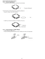
13.3.4. How to Install the IC
1. Place the solder a little on the land where the radiation GND pad on IC bottom is to be attached.
2. Place the solder a little on the land where IC pins are to be attached, then place the IC.
Note:
• When placing the IC, the positioning should be done very carefully.
3. Heat the IC with a hot air desoldering tool through the P.C.Board until the solder on IC bottom is melted.
Note:
• Be sure to place it precisely, controlling the air volume of the hot air desoldering tool.
4. After soldering, confirm there are no short and open circuits with visual inspection.
13.3.5. How to Remove a Solder Bridge
When a Solder Bridge is found after soldering the bottom of the IC, remove it with a soldering iron.
Summary of Contents for KX-TGA403LAT
Page 2: ...2 KX TG4021LAT KX TG4022LAT KX TG4023LAT KX TGA403LAT ...
Page 23: ...23 KX TG4021LAT KX TG4022LAT KX TG4023LAT KX TGA403LAT 4 9 Signal Route ...
Page 24: ...24 KX TG4021LAT KX TG4022LAT KX TG4023LAT KX TGA403LAT RF part signal route ...
Page 28: ...28 KX TG4021LAT KX TG4022LAT KX TG4023LAT KX TGA403LAT 8 1 2 Handset ...
Page 44: ...44 KX TG4021LAT KX TG4022LAT KX TG4023LAT KX TGA403LAT ...
Page 45: ...45 KX TG4021LAT KX TG4022LAT KX TG4023LAT KX TGA403LAT 11 1 2 Handset ...
Page 46: ...46 KX TG4021LAT KX TG4022LAT KX TG4023LAT KX TGA403LAT 11 1 3 Charger Unit ...
Page 65: ...65 KX TG4021LAT KX TG4022LAT KX TG4023LAT KX TGA403LAT Memo ...
Page 69: ...69 KX TG4021LAT KX TG4022LAT KX TG4023LAT KX TGA403LAT Memo ...
Page 76: ...76 KX TG4021LAT KX TG4022LAT KX TG4023LAT KX TGA403LAT Memo ...
Page 83: ...83 KX TG4021LAT KX TG4022LAT KX TG4023LAT KX TGA403LAT 16 4 Accessories A2 A3 A1 ...

